
Turn on suggestions
Auto-suggest helps you quickly narrow down your search results by suggesting possible matches as you type.
Showing results for
Please log in to access translation
Turn on suggestions
Auto-suggest helps you quickly narrow down your search results by suggesting possible matches as you type.
Showing results for
Community Tip - Did you know you can set a signature that will be added to all your posts? Set it here! X
- Community
- Creo+ and Creo Parametric
- 3D Part & Assembly Design
- vertically splitting a surface to draft in opposit...
Translate the entire conversation x
Please log in to access translation
Options
- Subscribe to RSS Feed
- Mark Topic as New
- Mark Topic as Read
- Float this Topic for Current User
- Bookmark
- Subscribe
- Mute
- Printer Friendly Page
vertically splitting a surface to draft in opposite directions
Jul 08, 2015
08:43 AM
- Mark as New
- Bookmark
- Subscribe
- Mute
- Subscribe to RSS Feed
- Permalink
- Notify Moderator
Please log in to access translation
Jul 08, 2015
08:43 AM
vertically splitting a surface to draft in opposite directions
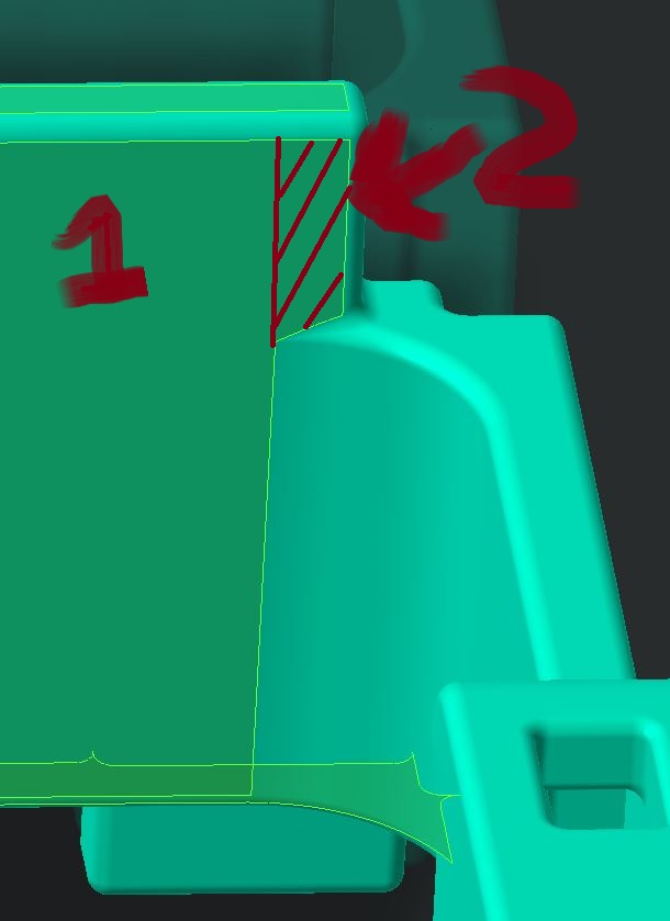
How can I vertically split a surface to draft in opposite directions? I have a feature that intersects a surface that creates an undercut if I pull the whole surface. I need to draft up to the feature and split it so the area above it will pull in the opposite direction. It will create a small mismatch, but this is acceptable.
Draft surface #1 in one direction and surface #2 in the other.
This thread is inactive and closed by the PTC Community Management Team. If you would like to provide a reply and re-open this thread, please notify the moderator and reference the thread. You may also use "Start a topic" button to ask a new question. Please be sure to include what version of the PTC product you are using so another community member knowledgeable about your version may be able to assist.
Solved! Go to Solution.
Labels:
- Labels:
-
General
ACCEPTED SOLUTION
Accepted Solutions
Jul 08, 2015
10:01 AM
- Mark as New
- Bookmark
- Subscribe
- Mute
- Subscribe to RSS Feed
- Permalink
- Notify Moderator
Please log in to access translation
Jul 08, 2015
10:01 AM
Jef,
If this is a native Creo part then this will be pretty simple, If this is an import model then you will need to spend some time manipulating surfaces...
In a perfect world, it goes like this...
First you need to remove the radii on the top, end, and bottom of the wall you're trying to draft. (need to work with square corners)
Then, "Sketch", or "Project" a curve onto the surface where you want to hinge the draft.
Then create you "Draft" feature using the hinge curve, with the "split at hinge" and "first side only" options. (or "second side only" whichever is appropriate)
Then put your radii back on.
In a not so perfect world... If the main surface is a sweep or some other non-plainer surface (or is an imported model), then a simple "draft" feature won't do the job...
In this case, you need to use the same projected curve as a trajectory and sweep the draft surface.
Then build the edge surfaces, merge it all together and solidify (remove) the material you don't want.
Then put your radii back on.
This can be pretty easy, or it can be a complete pain, but to do it right will take some effort.
Good Luck
Bernie
Bernie Gruman
Owner / Designer / Builder
www.GrumanCreations.com
3 REPLIES 3
Jul 08, 2015
10:01 AM
- Mark as New
- Bookmark
- Subscribe
- Mute
- Subscribe to RSS Feed
- Permalink
- Notify Moderator
Please log in to access translation
Jul 08, 2015
10:01 AM
Jef,
If this is a native Creo part then this will be pretty simple, If this is an import model then you will need to spend some time manipulating surfaces...
In a perfect world, it goes like this...
First you need to remove the radii on the top, end, and bottom of the wall you're trying to draft. (need to work with square corners)
Then, "Sketch", or "Project" a curve onto the surface where you want to hinge the draft.
Then create you "Draft" feature using the hinge curve, with the "split at hinge" and "first side only" options. (or "second side only" whichever is appropriate)
Then put your radii back on.
In a not so perfect world... If the main surface is a sweep or some other non-plainer surface (or is an imported model), then a simple "draft" feature won't do the job...
In this case, you need to use the same projected curve as a trajectory and sweep the draft surface.
Then build the edge surfaces, merge it all together and solidify (remove) the material you don't want.
Then put your radii back on.
This can be pretty easy, or it can be a complete pain, but to do it right will take some effort.
Good Luck
Bernie
Bernie Gruman
Owner / Designer / Builder
www.GrumanCreations.com
Jul 08, 2015
10:16 AM
- Mark as New
- Bookmark
- Subscribe
- Mute
- Subscribe to RSS Feed
- Permalink
- Notify Moderator
Please log in to access translation
Jul 08, 2015
10:16 AM
It's possible to split a single draft feature anywhere you want, in different directions and at different angles.
It's a bit involved and different than Bernie's sketch > project method. On the other hand, based on your pic, it may not cause a mismatch. In your picture, the border between area 1 and area two would be the split line?
I'll try to dig up some instructions I created some time ago for my designers.
Jul 08, 2015
10:47 AM
- Mark as New
- Bookmark
- Subscribe
- Mute
- Subscribe to RSS Feed
- Permalink
- Notify Moderator
Please log in to access translation
Jul 08, 2015
10:47 AM
Alright, I didn't find the instructions, but it's less involved than I remembered it being. Perhaps it was the shape that was really giving me fits instead of the draft process itself.
There are actually two methods. The method to use depends on the draft hinge (where area 1 and area 2 meet on your pic).
Method one cuts back material from the split line (in blue). You can see the original shape in red.
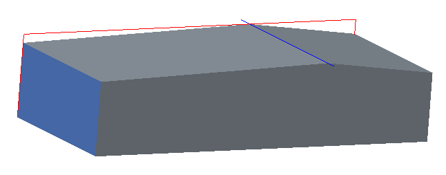
Method two grows material up from the intersection of the blue surface and the top. If it's not split in the middle, there is a chance of mismatch. (Of course you could calculate out the exact angle each side needs to be based on where the split occurs on the overall surface size.)
The original shape, again, is in red.

Let me know which is the method you'd like and I'll put up the instructions.


