
Turn on suggestions
Auto-suggest helps you quickly narrow down your search results by suggesting possible matches as you type.
Showing results for
Please log in to access translation
Turn on suggestions
Auto-suggest helps you quickly narrow down your search results by suggesting possible matches as you type.
Showing results for
Community Tip - Did you get an answer that solved your problem? Please mark it as an Accepted Solution so others with the same problem can find the answer easily. X
- Community
- Creo+ and Creo Parametric
- Analysis
- Re: Flat pattern of a part which was created using...
Translate the entire conversation x
Please log in to access translation
Options
- Subscribe to RSS Feed
- Mark Topic as New
- Mark Topic as Read
- Float this Topic for Current User
- Bookmark
- Subscribe
- Mute
- Printer Friendly Page
Flat pattern of a part which was created using a Swept Blend
Jun 05, 2012
07:06 AM
- Mark as New
- Bookmark
- Subscribe
- Mute
- Subscribe to RSS Feed
- Permalink
- Notify Moderator
Please log in to access translation
Jun 05, 2012
07:06 AM
Flat pattern of a part which was created using a Swept Blend
Hello, everyone!
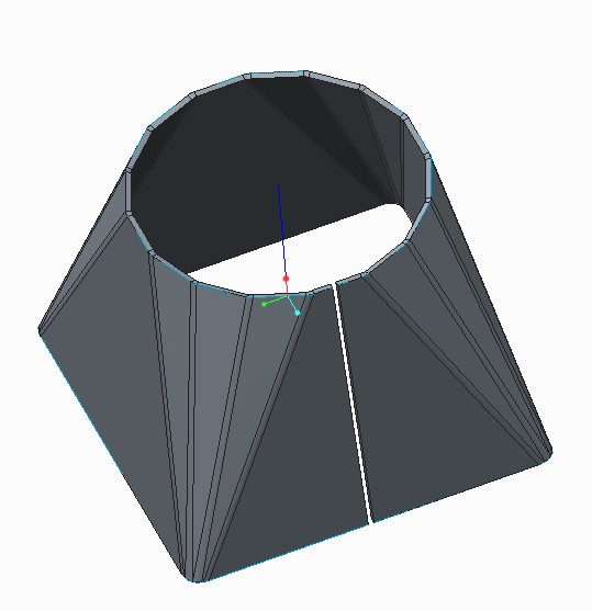
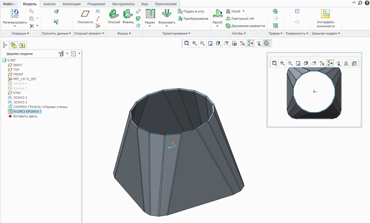
I would like to get a flat pattern of a part, which was created using a Swept Blend in the Sheetmetal Module of Creo Parametric.
This Swept Blend consist of two sections. Each of them has the same quantity of segments. I used a Convert Tool to add bends on sharp edges to round sharp edges.
But when I was trying to create a flat pattern of this part, Creo displayed a warning message that there is no geometry to unbend.
Does anybody know how to solve this problem?
I attached a picture and a model of this part.
Thank you in advance.
Best regards, Vladimir.
This thread is inactive and closed by the PTC Community Management Team. If you would like to provide a reply and re-open this thread, please notify the moderator and reference the thread. You may also use "Start a topic" button to ask a new question. Please be sure to include what version of the PTC product you are using so another community member knowledgeable about your version may be able to assist.
Solved! Go to Solution.
Labels:
- Labels:
-
General
ACCEPTED SOLUTION
Accepted Solutions
Jun 08, 2012
05:31 AM
- Mark as New
- Bookmark
- Subscribe
- Mute
- Subscribe to RSS Feed
- Permalink
- Notify Moderator
Please log in to access translation
Jun 08, 2012
05:31 AM
Hello, Davor, Antonius!
Thank you for your help.
Eventually I managed to get the flat pattern of my model.
The problem was that some of the sides of my part were twisted. That happend because the lines on the opposite sections, which I used to make the Boundary Blend, weren't parallel to each other.
Best regards, Vladimir.
19 REPLIES 19
Jun 05, 2012
12:41 PM
- Mark as New
- Bookmark
- Subscribe
- Mute
- Subscribe to RSS Feed
- Permalink
- Notify Moderator
Please log in to access translation
Jun 05, 2012
12:41 PM
There may not be enough "flange" along the bottom through the radii to unbend. Maybe try making the triangles parallograms instead.
Jun 06, 2012
02:49 AM
- Mark as New
- Bookmark
- Subscribe
- Mute
- Subscribe to RSS Feed
- Permalink
- Notify Moderator
Please log in to access translation
Jun 06, 2012
02:49 AM
Hello, Antonius.
Thank you for you advice. I've tried it but unfortunately it didn't help.
I also attempted to create this part using the Boundary Blend tool. The result was the same. Creo displayed a warning message that there is no geometry for unbending.
That's strange, because I imported much more complicated part which was made in Inventor 2012 and got its flat pattern without any difficulties.
Best regards, Vladimir.
Jun 06, 2012
01:24 PM
- Mark as New
- Bookmark
- Subscribe
- Mute
- Subscribe to RSS Feed
- Permalink
- Notify Moderator
Please log in to access translation
Jun 06, 2012
01:24 PM
I played with your part a little bit last night. I don't have the full version of sheet metal appearantly because I couldn't blend with thickness or radii. Makes the default sheetmetal kind of useless for me although I do a lot of boxes and panels. I just rarely need to unfold anything so no biggy. I know how to calculate my own bend allowances.
As for why your part won't unfold, I do not know. I was a bit surprised as to how the two sketches meshed with a few extra lines connecting them.
I think I'll stick to the simple stuff for now. So many things I know are there but just can't find it on the new interface. Give me the old 2000i legacy intereface and I can fly 
Jun 06, 2012
02:57 AM
- Mark as New
- Bookmark
- Subscribe
- Mute
- Subscribe to RSS Feed
- Permalink
- Notify Moderator
Please log in to access translation
Jun 06, 2012
02:57 AM
Hi Vladimir,
You have same problem answered here http://communities.ptc.com/message/165189#165189
You also have part that can be unbent there for download.
Cheers
Jun 06, 2012
03:56 AM
- Mark as New
- Bookmark
- Subscribe
- Mute
- Subscribe to RSS Feed
- Permalink
- Notify Moderator
Please log in to access translation
Jun 06, 2012
03:56 AM
Hello, Davor.
Thank you for your answer.
Actually, I've seen your model before. That's great. I repeated it step by step and flatten it.
That is the reason why I attempted to use the Boundary Blend tool for my part.
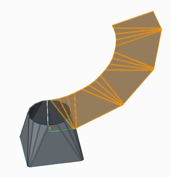
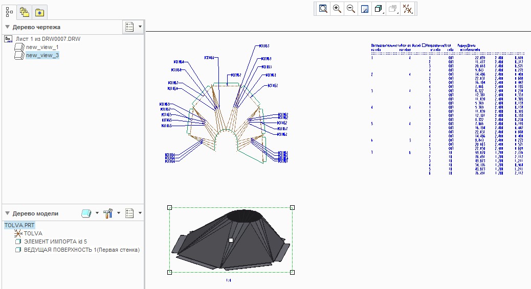
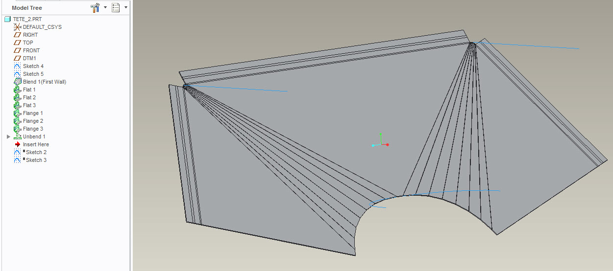
But I would like to exchange every conical bend for four angled bends in order to create a Table of Bends (as you can see in the picture above). I would like to show bend lines in a view with a flat pattern and point the value of the angle of each bend in the table of bends.
When I try to use your technique for my part it doesn't work. I can't flatten the model.
Best regards, Vladimir.
P.S.: There is an option in Lofted Bends tool in SolidWorks which is called Bend Line Control. It enables you to set the number of bend lines for conical bend.
That's what I'm looking for in Creo Parametric.
Jun 06, 2012
12:03 PM
- Mark as New
- Bookmark
- Subscribe
- Mute
- Subscribe to RSS Feed
- Permalink
- Notify Moderator
Please log in to access translation
Jun 06, 2012
12:03 PM
I guess you need to put it in "idea" area as a enhancment request.
Maybe you can make quilt from outer surface and flatten it then use Flatten Quilt Deformation tool on solid part. To me its too much work. PTC must make something simpler.
Jun 08, 2012
05:31 AM
- Mark as New
- Bookmark
- Subscribe
- Mute
- Subscribe to RSS Feed
- Permalink
- Notify Moderator
Please log in to access translation
Jun 08, 2012
05:31 AM
Hello, Davor, Antonius!
Thank you for your help.
Eventually I managed to get the flat pattern of my model.
The problem was that some of the sides of my part were twisted. That happend because the lines on the opposite sections, which I used to make the Boundary Blend, weren't parallel to each other.
Best regards, Vladimir.
Jun 08, 2012
11:07 AM
- Mark as New
- Bookmark
- Subscribe
- Mute
- Subscribe to RSS Feed
- Permalink
- Notify Moderator
Please log in to access translation
Jun 08, 2012
11:07 AM
Vladimir, I am happy that you achieved your goal.
The error you found explains why I saw the extra extension lines... and in hindsight, I remember seeing an odd alignment along the top edge of your part. Now I understand what to look for.
Thank you for reporting your findings.
Aug 28, 2014
10:25 AM
- Mark as New
- Bookmark
- Subscribe
- Mute
- Subscribe to RSS Feed
- Permalink
- Notify Moderator
Please log in to access translation
Aug 28, 2014
10:25 AM
Hi Vladimir,
I'm with problem in a part similar. How do you resolved?
best regards,
Cesar
Aug 28, 2014
10:45 AM
- Mark as New
- Bookmark
- Subscribe
- Mute
- Subscribe to RSS Feed
- Permalink
- Notify Moderator
Please log in to access translation
Aug 28, 2014
02:18 PM
- Mark as New
- Bookmark
- Subscribe
- Mute
- Subscribe to RSS Feed
- Permalink
- Notify Moderator
Please log in to access translation
Aug 28, 2014
02:18 PM
Hi Antonius,
Thank you for your answer. But I was unable to do.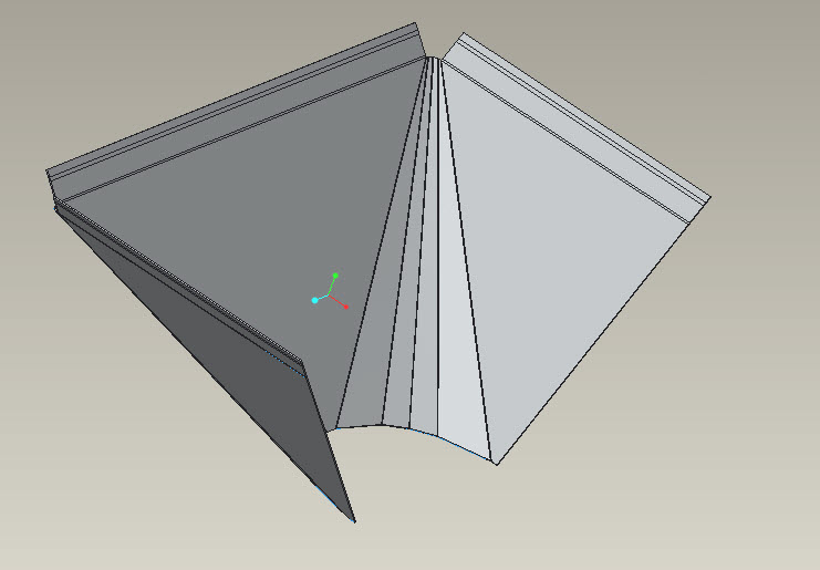
Best regards,
Cesar
Aug 28, 2014
02:33 PM
- Mark as New
- Bookmark
- Subscribe
- Mute
- Subscribe to RSS Feed
- Permalink
- Notify Moderator
Please log in to access translation
Aug 28, 2014
02:33 PM
If the faces of those corners are not perfectly flat, it cannot unbend the part.
Aug 28, 2014
02:50 PM
- Mark as New
- Bookmark
- Subscribe
- Mute
- Subscribe to RSS Feed
- Permalink
- Notify Moderator
Please log in to access translation
Aug 28, 2014
02:50 PM
Here is another relevant post:
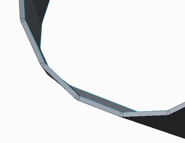
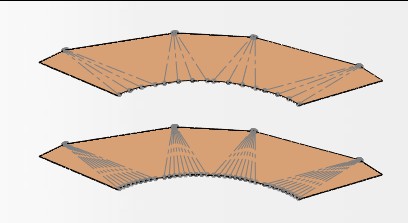
One tool to find the problem faces is the option:
config - mesh_spline_surf yes
If you see lines through a surface in wireframe display mode, the surface is twisted.
Aug 28, 2014
03:44 PM
- Mark as New
- Bookmark
- Subscribe
- Mute
- Subscribe to RSS Feed
- Permalink
- Notify Moderator
Please log in to access translation
Aug 28, 2014
03:44 PM
I did do, but I don't know how. I made a copy an exemple.
Thank you.
Aug 28, 2014
04:01 PM
- Mark as New
- Bookmark
- Subscribe
- Mute
- Subscribe to RSS Feed
- Permalink
- Notify Moderator
Please log in to access translation
Aug 28, 2014
04:01 PM
See - Easy! 
Aug 28, 2014
04:34 PM
- Mark as New
- Bookmark
- Subscribe
- Mute
- Subscribe to RSS Feed
- Permalink
- Notify Moderator
Please log in to access translation
Aug 28, 2014
04:34 PM
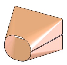
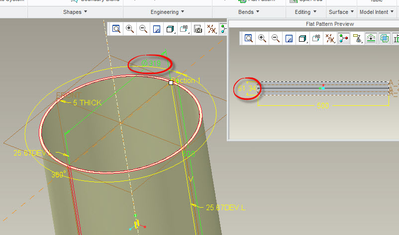
another question, do you know why (figure)?
Best regardes
Aug 28, 2014
05:50 PM
- Mark as New
- Bookmark
- Subscribe
- Mute
- Subscribe to RSS Feed
- Permalink
- Notify Moderator
Please log in to access translation
Aug 28, 2014
05:50 PM
It all depends on how this was made. It meets the development length x 2.
If this is a full version Creo file, we can have a look. You can post files using the advanced editor.
Aug 29, 2014
01:34 PM
- Mark as New
- Bookmark
- Subscribe
- Mute
- Subscribe to RSS Feed
- Permalink
- Notify Moderator
Please log in to access translation
Aug 29, 2014
01:34 PM
Thank you!
César
Aug 29, 2014
04:40 PM
- Mark as New
- Bookmark
- Subscribe
- Mute
- Subscribe to RSS Feed
- Permalink
- Notify Moderator
Please log in to access translation
Aug 29, 2014
04:40 PM
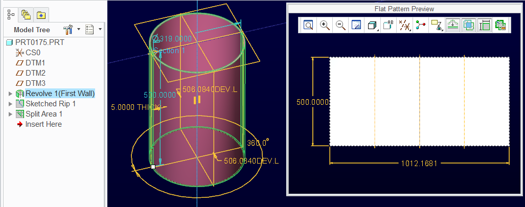
This is what the cylinder part should look like in flat pattern.
I am using the default Y-Factor.
Notice that I used a revolve to get the initial shape.
Then a rip to separate this; and the Split Area to have the unfold happened across from the rip.
Announcements


Top Tags
