
Turn on suggestions
Auto-suggest helps you quickly narrow down your search results by suggesting possible matches as you type.
Showing results for
Please log in to access translation
Turn on suggestions
Auto-suggest helps you quickly narrow down your search results by suggesting possible matches as you type.
Showing results for
Community Tip - Need to share some code when posting a question or reply? Make sure to use the "Insert code sample" menu option. Learn more! X
- Community
- Creo+ and Creo Parametric
- Analysis
- Re: Help in Mechanism
Translate the entire conversation x
Please log in to access translation
Options
- Subscribe to RSS Feed
- Mark Topic as New
- Mark Topic as Read
- Float this Topic for Current User
- Bookmark
- Subscribe
- Mute
- Printer Friendly Page
Help in Mechanism
Jun 23, 2015
12:24 PM
- Mark as New
- Bookmark
- Subscribe
- Mute
- Subscribe to RSS Feed
- Permalink
- Notify Moderator
Please log in to access translation
Jun 23, 2015
12:24 PM
Help in Mechanism
Details in this pic.I want that extruded portion should rotate the cylinder when it makes contact with it and then carry it in the later motion.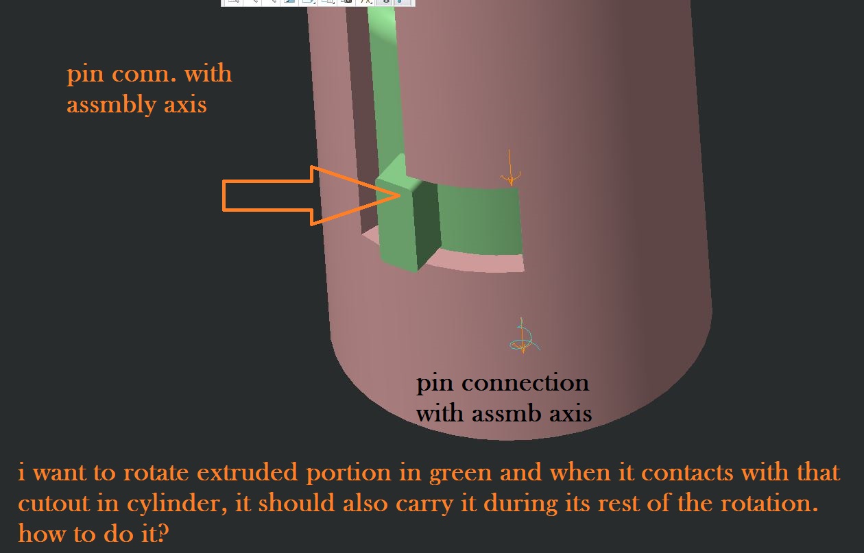
This thread is inactive and closed by the PTC Community Management Team. If you would like to provide a reply and re-open this thread, please notify the moderator and reference the thread. You may also use "Start a topic" button to ask a new question. Please be sure to include what version of the PTC product you are using so another community member knowledgeable about your version may be able to assist.
Labels:
- Labels:
-
General
8 REPLIES 8
Jun 24, 2015
02:43 AM
- Mark as New
- Bookmark
- Subscribe
- Mute
- Subscribe to RSS Feed
- Permalink
- Notify Moderator
Please log in to access translation
Jun 24, 2015
02:43 AM
My first guess is to use a slot connection. You will need to model a curve in one part and a point on the other.With a slot connection the point will slide along the curve. You can specify (I think) a coefficient of restitution at the end points of the curve, so that there is some dampening when the point hits the end of the curve. I haven't played around with slot curves in a while, so I'm not sure how this works today.
Jun 24, 2015
01:36 PM
- Mark as New
- Bookmark
- Subscribe
- Mute
- Subscribe to RSS Feed
- Permalink
- Notify Moderator
Please log in to access translation
Jun 24, 2015
01:36 PM
Shouldn't be one body fixed for slot connection? Here both of them are given pin connection as each of them rotates.
Jun 24, 2015
07:46 PM
- Mark as New
- Bookmark
- Subscribe
- Mute
- Subscribe to RSS Feed
- Permalink
- Notify Moderator
Please log in to access translation
Jun 24, 2015
07:46 PM
I find it easier to simply mimic the motion with servo motors using specific timelines.
in this case, use a rack and pinion gear connection to a phantom servo motor and then a separate servo motor for the rotary motion.
Not elegant, but certainly achievable.
Jun 25, 2015
04:40 AM
- Mark as New
- Bookmark
- Subscribe
- Mute
- Subscribe to RSS Feed
- Permalink
- Notify Moderator
Please log in to access translation
Jun 25, 2015
04:40 AM
Yes at very first place i had a thought of using two different servo motors and then time them accordingly. But i thought there has to be some real time way where they contact each other and start rotating. Thanks for your feedback.
Jun 25, 2015
04:09 AM
- Mark as New
- Bookmark
- Subscribe
- Mute
- Subscribe to RSS Feed
- Permalink
- Notify Moderator
Please log in to access translation
Jun 25, 2015
04:09 AM
Here I made a test with a slot and two rotating parts. Works fine, the model is redundant, so I had some accuracy issues with the wrapped curve representing the slot. This can be overcome with some more detailed modeling...
Jun 25, 2015
04:41 AM
- Mark as New
- Bookmark
- Subscribe
- Mute
- Subscribe to RSS Feed
- Permalink
- Notify Moderator
Please log in to access translation
Jun 25, 2015
04:41 AM
This one seems good i will try with my model too.Thank you 
Jun 25, 2015
04:44 AM
- Mark as New
- Bookmark
- Subscribe
- Mute
- Subscribe to RSS Feed
- Permalink
- Notify Moderator
Please log in to access translation
Jun 25, 2015
04:44 AM
I didn't manage to create "end stops" for the slot-connection itself. But this should be possible to achieve with max/min values enabled on the joints connecting the shafts.
Jun 25, 2015
04:57 AM
- Mark as New
- Bookmark
- Subscribe
- Mute
- Subscribe to RSS Feed
- Permalink
- Notify Moderator
Please log in to access translation
Jun 25, 2015
04:57 AM
Hmm i gave it a try but don't know what's wrong with me.
This is the flow :
1) Cylinder assembled with pin constraint to assembly axis.
2) cylinder handle (green)..given pin connection with assembly axis and slot follower
while rotating both of them rotates i dont know why!!!
Announcements


Top Tags
