
Solved
Mapped meshes and spheres
Hello,
A quarter cylinder is easy
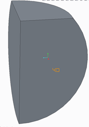
But what about a quarter sphere with the top chopped off?
The model really is as simple as it looks.
I can't be looking at the meshing problem in the right way.
Any thoughts
Thanks

Hello,
A quarter cylinder is easy
But what about a quarter sphere with the top chopped off?
The model really is as simple as it looks.
I can't be looking at the meshing problem in the right way.
Any thoughts
Thanks
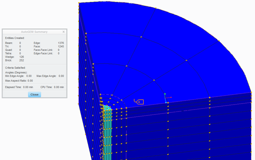
OK,
example 2 (volume regions only, but sphere with the top chopped off).
regards
paul
Enter your E-mail address. We'll send you an e-mail with instructions to reset your password.