
Turn on suggestions
Auto-suggest helps you quickly narrow down your search results by suggesting possible matches as you type.
Showing results for
Please log in to access translation
Turn on suggestions
Auto-suggest helps you quickly narrow down your search results by suggesting possible matches as you type.
Showing results for
- Community
- Creo+ and Creo Parametric
- Analysis
- Re: Timing Screw
Translate the entire conversation x
Please log in to access translation
Options
- Subscribe to RSS Feed
- Mark Topic as New
- Mark Topic as Read
- Float this Topic for Current User
- Bookmark
- Subscribe
- Mute
- Printer Friendly Page
Timing Screw
Jan 21, 2014
10:50 PM
- Mark as New
- Bookmark
- Subscribe
- Mute
- Subscribe to RSS Feed
- Permalink
- Notify Moderator
Please log in to access translation
Jan 21, 2014
10:50 PM
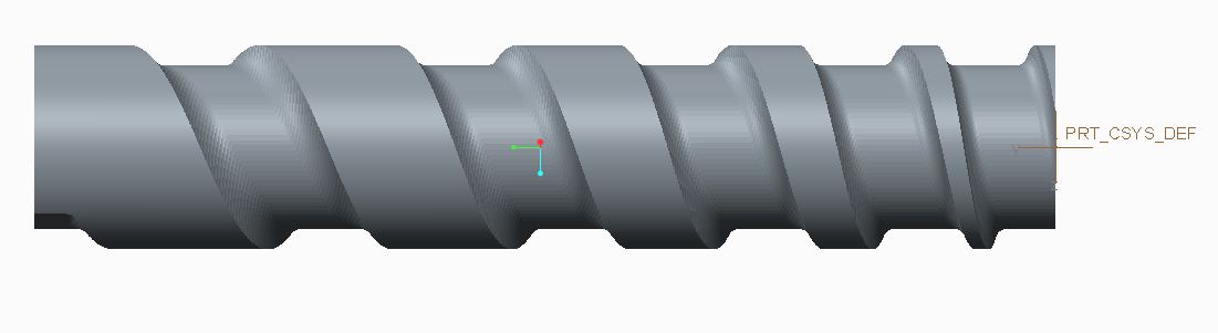
Timing Screw
Dear
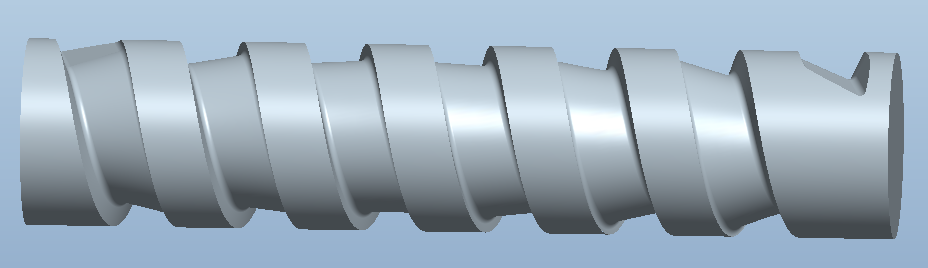
I see one function to design Timing Screw is good
https://www.youtube.com/watch?v=gdRKmJHwPvI
How in Creo have this function:
The fuction is not sweep or Var section sweep
This function is: Sweep with variable pitch cut from one extrude body (In creo just sweep from section, this is sweep cut from body)
Please help & discuss how to do in Creo
Thanks & Regards
This thread is inactive and closed by the PTC Community Management Team. If you would like to provide a reply and re-open this thread, please notify the moderator and reference the thread. You may also use "Start a topic" button to ask a new question. Please be sure to include what version of the PTC product you are using so another community member knowledgeable about your version may be able to assist.
Labels:
- Labels:
-
General
25 REPLIES 25
Jan 22, 2014
08:23 AM
- Mark as New
- Bookmark
- Subscribe
- Mute
- Subscribe to RSS Feed
- Permalink
- Notify Moderator
Please log in to access translation
Jan 22, 2014
08:23 AM
You should be able to create a graph to change the angle (rotate) the section as it moves down the trajectory.
Jan 22, 2014
08:48 AM
- Mark as New
- Bookmark
- Subscribe
- Mute
- Subscribe to RSS Feed
- Permalink
- Notify Moderator
Please log in to access translation
Jan 22, 2014
08:48 AM
Here's a quick example of what I mean.
Jan 22, 2014
03:13 PM
- Mark as New
- Bookmark
- Subscribe
- Mute
- Subscribe to RSS Feed
- Permalink
- Notify Moderator
Please log in to access translation
Jan 22, 2014
03:13 PM
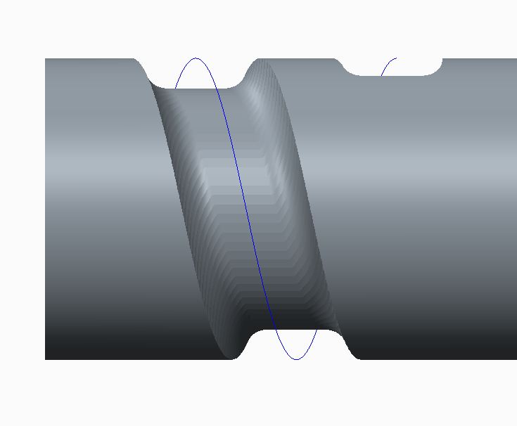
If is follows a constant angle change of the "tool" it could be a variable section sweep using trajpar along a spiral guide path (origin). The path would incorporate the pitch variation, if needed, by wrapping a sketch onto the cylinder.
Jan 22, 2014
03:51 PM
- Mark as New
- Bookmark
- Subscribe
- Mute
- Subscribe to RSS Feed
- Permalink
- Notify Moderator
Please log in to access translation
Jan 22, 2014
03:51 PM
I've uploaded this file (WF5) if anyone wants to see it.
http://communities.ptc.com/servlet/JiveServlet/downloadBody/4862-102-1-7108/prt0001.prt.1.zip
Jan 22, 2014
04:51 PM
- Mark as New
- Bookmark
- Subscribe
- Mute
- Subscribe to RSS Feed
- Permalink
- Notify Moderator
Please log in to access translation
Jan 22, 2014
04:51 PM
You can attach files to post if you use the advanced editor (upper right).
Jan 22, 2014
06:38 PM
- Mark as New
- Bookmark
- Subscribe
- Mute
- Subscribe to RSS Feed
- Permalink
- Notify Moderator
Please log in to access translation
Jan 22, 2014
06:38 PM
Ah, much better. Thank you!
Jan 22, 2014
08:41 PM
- Mark as New
- Bookmark
- Subscribe
- Mute
- Subscribe to RSS Feed
- Permalink
- Notify Moderator
Please log in to access translation
Jan 22, 2014
08:41 PM
I have worked on a problem like this before and found that core Creo does not do this very well at all. It can do a 2D cut with ease with many options, but to remove a 3D tool, even something as simple as a ball end mill, it simply doesn't work right. I suspect you need the manufacturing extension to get this right, and even with that, I am not sure you can get this result.
Jan 22, 2014
08:56 PM
- Mark as New
- Bookmark
- Subscribe
- Mute
- Subscribe to RSS Feed
- Permalink
- Notify Moderator
Please log in to access translation
Jan 22, 2014
08:56 PM
This might make it clear or just muddy the waters... but if I extrude any section along Tom's model, it removes more material. This would happened continuously along the entire path.
If this can be done in core Creo without faceting the cut surface, I would love to know about it.
This is a very real condition anytime you add a mill to a rotating cylinder. Think about a grind wheel that is machining grooves into a cylinder mounted to a lathe. How would you do that?
Jan 22, 2014
10:53 PM
- Mark as New
- Bookmark
- Subscribe
- Mute
- Subscribe to RSS Feed
- Permalink
- Notify Moderator
Please log in to access translation
Jan 22, 2014
10:53 PM
I think this form can be generated by single point cutting. Mill out the bulk of the material and then single-point the remainder.
A flat bottom cutter won't work anyway as the the angle between the walls and the bottom changes from 90 degrees.
Jan 22, 2014
10:56 PM
- Mark as New
- Bookmark
- Subscribe
- Mute
- Subscribe to RSS Feed
- Permalink
- Notify Moderator
Please log in to access translation
Jan 22, 2014
10:56 PM
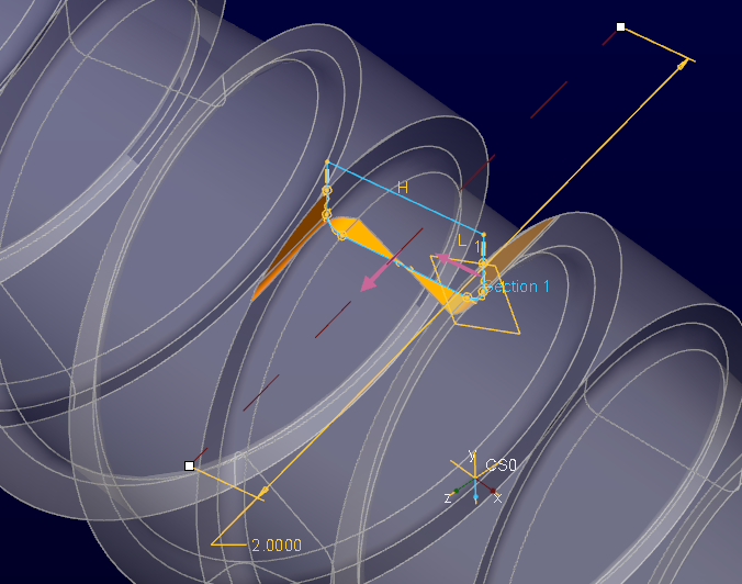
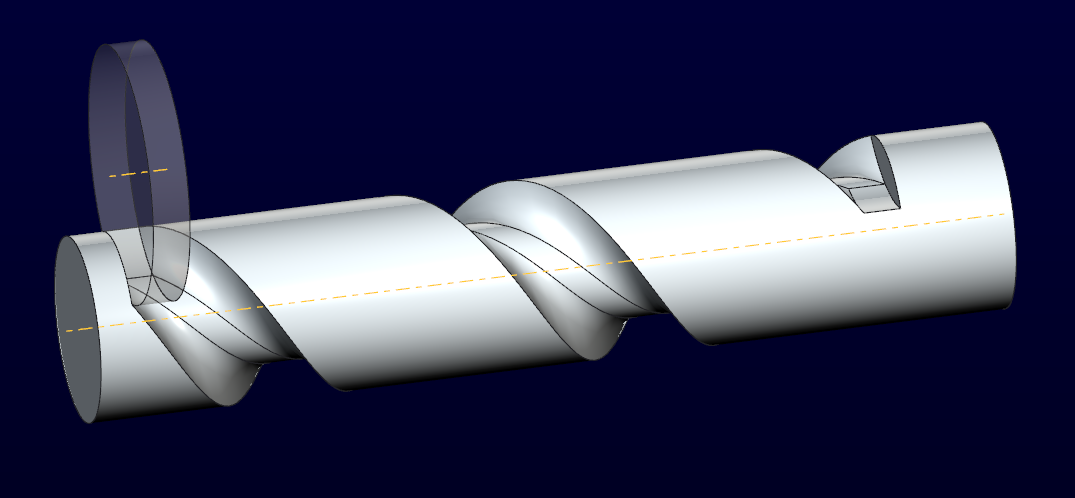
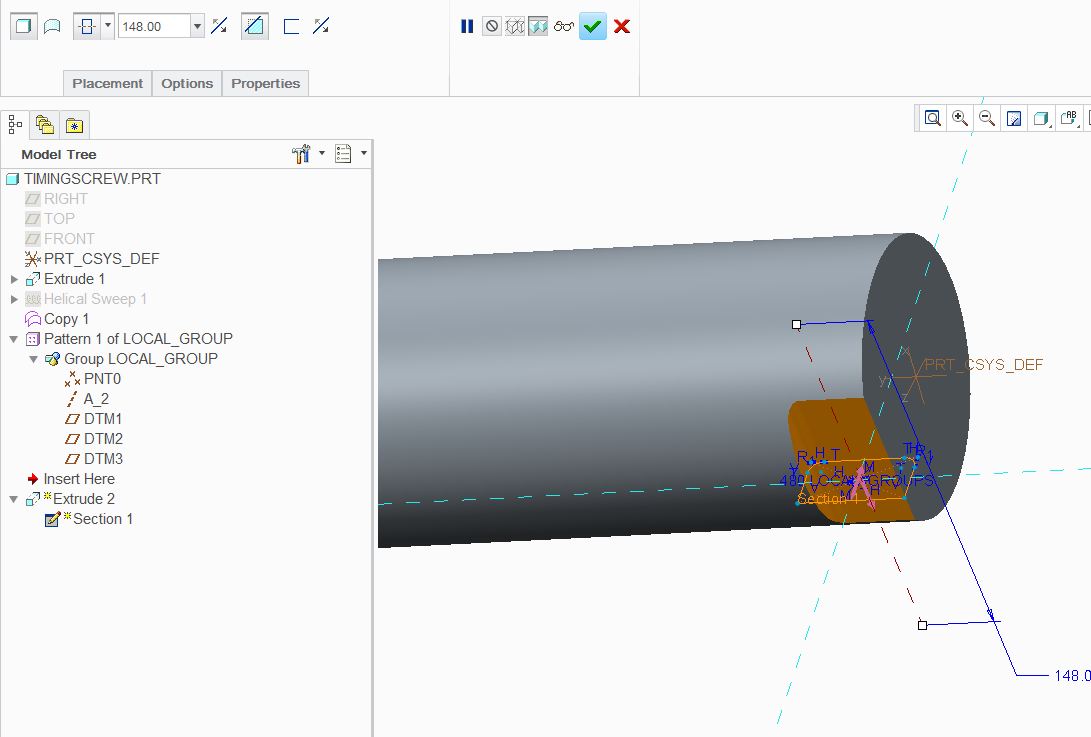
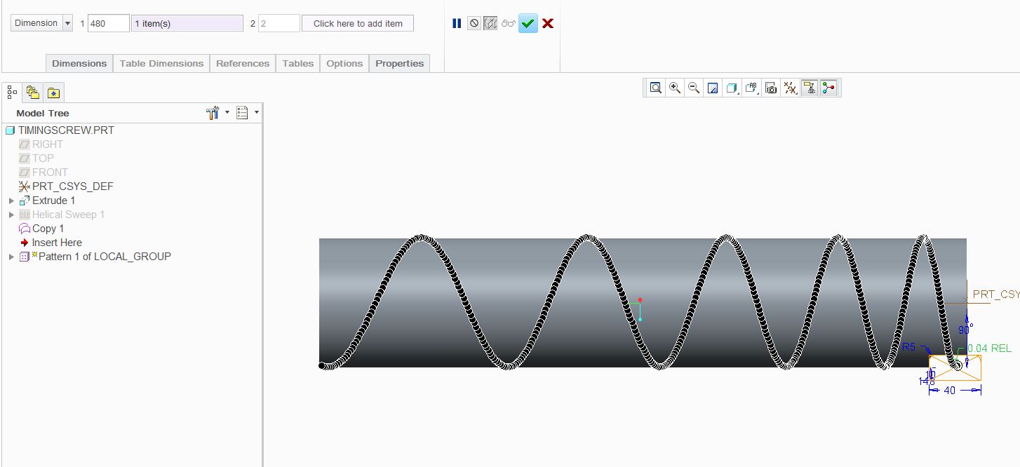
Dear
I will do follow step
- 1/ Make a ref point in helical curve (to get dimension to pattern) & datum plan
- 2/Cut extrude at datum plan through point ref
- 3/ Group: point, extrude, datum plan together
- 4/ Pattern folllow dimension, click dim of point
Please see the attach file & piture below
Link download files part in creo2.0:http://upfile.vn/ivQT/timing_screw.zip
However: if want to exactly, must pattern big number
Thanks & regrads
Jan 22, 2014
11:19 PM
- Mark as New
- Bookmark
- Subscribe
- Mute
- Subscribe to RSS Feed
- Permalink
- Notify Moderator
Please log in to access translation
Jan 22, 2014
11:19 PM
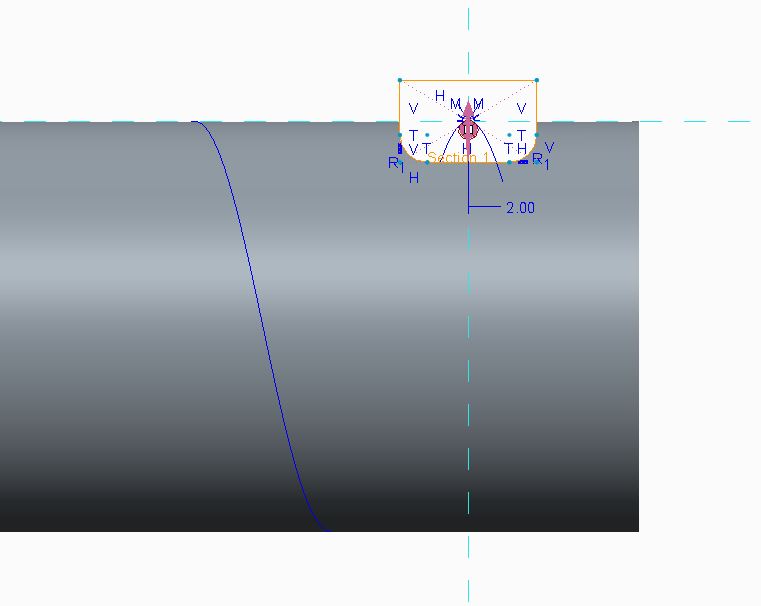
Does the angle of the flat surface need to change angles like in the video?
I did just figure out how to do a constant shape without having to pattern it by changing the sweep normals.
For instance, the see-through disk is a grinding wheel. The shaft is on a lathe.
First I sweep the section of the grind wheel along the helix, be it constant or variable; but it has an orientation along the axis instead of the origin helix.
Next, I sweep the round part of the disk; the "()" section, this time with the sketch normal to the axis of rotation (lathe).
Last, I pattern once the last sweep to provide the offset for the grinding wheel's thickness.
These 3 steps will make the part accurate as machined. I don't know how fillets may complicate this operation.
In my 1st attempt I also used a pattern method. So not satisfying 
I remember leaving a "wormholed" cylinder with facets one time. It bugs me to this day.
Jan 22, 2014
11:27 PM
- Mark as New
- Bookmark
- Subscribe
- Mute
- Subscribe to RSS Feed
- Permalink
- Notify Moderator
Please log in to access translation
Jan 22, 2014
11:27 PM
Dear
Please attach new file more perfect
http://upfile.vn/a7zi/timing_screw_new1.zip
This way, if any else please share
Thanks
Jan 22, 2014
11:59 PM
- Mark as New
- Bookmark
- Subscribe
- Mute
- Subscribe to RSS Feed
- Permalink
- Notify Moderator
Please log in to access translation
Jan 22, 2014
11:59 PM
Do you have the full version of Creo 2.0 Binh?
Jan 23, 2014
12:13 AM
- Mark as New
- Bookmark
- Subscribe
- Mute
- Subscribe to RSS Feed
- Permalink
- Notify Moderator
Please log in to access translation
Jan 23, 2014
12:13 AM

Creo 2.0 full version attached
variable pitch (wrapped arc sketch)
see sweep section orientation for controlling the cut orientations.
This represent a grind operation. This can be adapted for other shaped... however I am still not sure how rounds will translate. The pattern method will compare the shapes for accuracy.
Jan 22, 2014
11:42 PM
- Mark as New
- Bookmark
- Subscribe
- Mute
- Subscribe to RSS Feed
- Permalink
- Notify Moderator
Please log in to access translation
Jan 22, 2014
11:42 PM
Just saw what they do. Interesting.
http://www.youtube.com/watch?v=lDafdnAi-Z0
Kinsley Inc Turning and Grouping Timing Screws
http://www.youtube.com/watch?v=P9H9-5PkFOM
CNC Router Cutting Plastic Feedscrew
Jan 22, 2014
11:58 PM
- Mark as New
- Bookmark
- Subscribe
- Mute
- Subscribe to RSS Feed
- Permalink
- Notify Moderator
Please log in to access translation
Jan 22, 2014
11:58 PM
That could make you dizzy after a while 
Jan 23, 2014
12:30 AM
- Mark as New
- Bookmark
- Subscribe
- Mute
- Subscribe to RSS Feed
- Permalink
- Notify Moderator
Please log in to access translation
Jan 23, 2014
12:30 AM
Dear David Schenken
The bottle many kind of shape
how we will do other shape with your way?
Thanks
Jan 23, 2014
01:54 AM
- Mark as New
- Bookmark
- Subscribe
- Mute
- Subscribe to RSS Feed
- Permalink
- Notify Moderator
Please log in to access translation
Jan 23, 2014
01:54 AM
Hi
Let the surface more smooth (for cutting machine 4X)
follow step with tool boundary for multy section:
Now the surface smooth
Thanks
Jan 23, 2014
02:00 AM
- Mark as New
- Bookmark
- Subscribe
- Mute
- Subscribe to RSS Feed
- Permalink
- Notify Moderator
Please log in to access translation
Jan 23, 2014
02:00 AM
Nice solution!
Jan 19, 2015
03:01 PM
- Mark as New
- Bookmark
- Subscribe
- Mute
- Subscribe to RSS Feed
- Permalink
- Notify Moderator
Please log in to access translation
Jan 19, 2015
03:01 PM
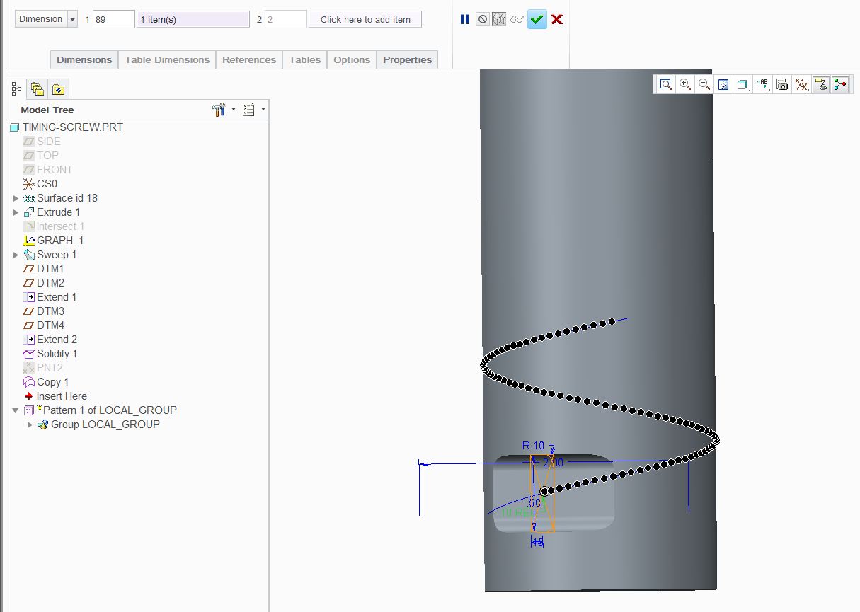
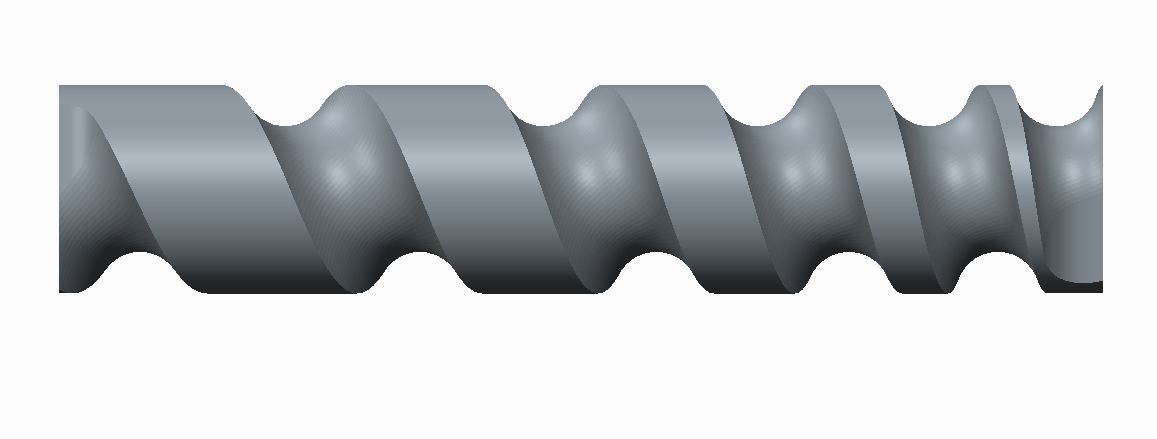
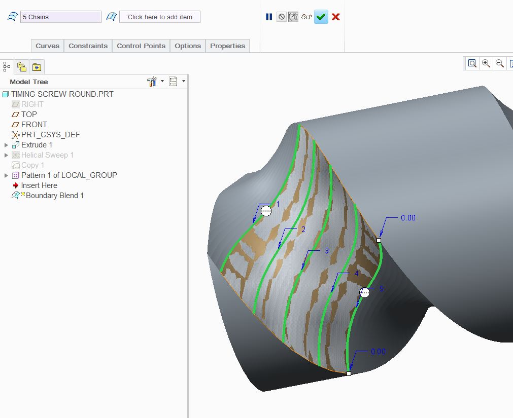
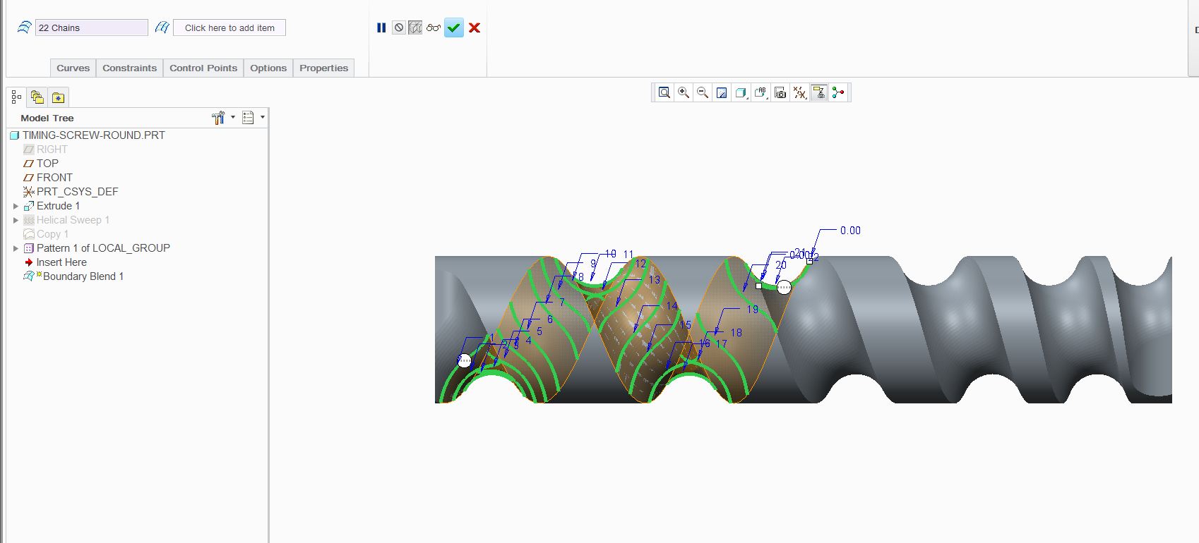
I know this is an old thread but I forgot about it and came up with the same solution... again.
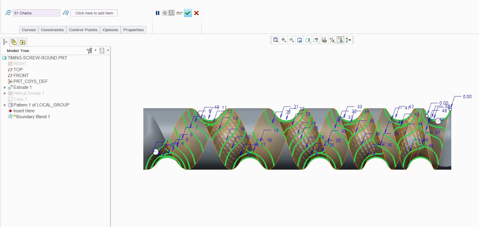
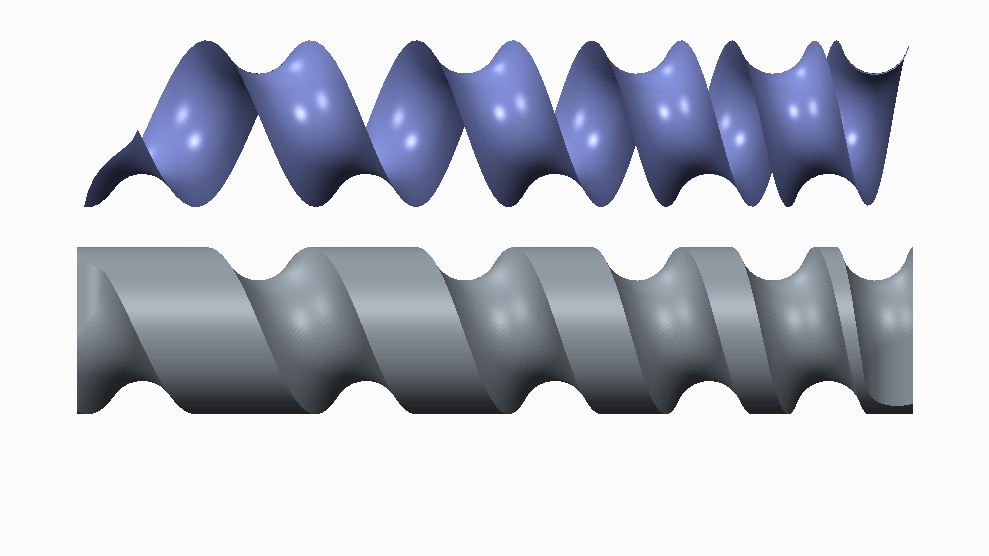
There are some tricks to making the surface smooth when directions change, but in general, boundary blends are probably one of the cleanest solution for timing screws available today.
Here's hoping that one day PTC will have swept solid cuts available in core Creo.
This timing screw was created using a pattern of 40 instances per revolution (9 degrees). Between the non-motion to rotation of the "specimen", the 9 degrees was divided in half for a smoother transition. Once the boundary blend was created (a single feature), the surface was offset to account for the "scalloped edge" depth. The offset can also add desired clearance. The ends of the "master" were also extended to make sure the blended splines were similar in length from the start. A significant length change from spline to spline will cause other artifacts along the surface. You can still see the transition where the part starts to rotate. See if you can pick up these tips in this video:
Be sure to go to YouTube and set the video to HD.
Jan 30, 2014
10:53 AM
- Mark as New
- Bookmark
- Subscribe
- Mute
- Subscribe to RSS Feed
- Permalink
- Notify Moderator
Please log in to access translation
Jan 30, 2014
10:53 AM
It appears solidquirks can sweep a solid body along another solid body as a cut. something Pro/E should have been able to do long ago. You can sweep cuts in Pro/E, sure, but the geometry you get will not be what a real cutting tool will create. Sometimes it's close, sometimes not. This thread is a perfect example of why we need this. So, PTC, how about quit monkeying with the GUI and give us features we can use?
http://help.solidworks.com/2014/English/solidworks/sldworks/hidd_dve_feat_sweep.htm
http://help.solidworks.com/2012/English/SolidWorks/sldworks/HIDD_DVE_FEAT_SWEEP.htm
Jan 30, 2014
04:00 PM
- Mark as New
- Bookmark
- Subscribe
- Mute
- Subscribe to RSS Feed
- Permalink
- Notify Moderator
Please log in to access translation
Jan 30, 2014
04:00 PM
I would think that the manufacturing extension does this just fine. Problem is, we as engineers are trying to tell manufacturing what to do but not how to do it. Not allowing core Creo to create an accurate model for these processes is a huge oversight in my view. It is a rare occurrence and certainly doesn't justify buying the manufacturing extension for 99% of users. Therefore, PTC's logic puts the cart before the horse and thereby creating a communication breakdown between design intent and fabrication.
Jan 30, 2014
05:46 PM
- Mark as New
- Bookmark
- Subscribe
- Mute
- Subscribe to RSS Feed
- Permalink
- Notify Moderator
Please log in to access translation
Jan 30, 2014
05:46 PM
I agree. I believe WE the Designers and Engineers need to be able to 100% describe the geometry we want, and will get using a certain 3D shape (not 2D section), and that Pro/MANUFACTURING should only need to do whatever tool geometry and toolpath are needed to get that geometry. If we cannot produce the geometry we need on our end, how can we, at the asembly level, know if the geometry will work? These timing screws are being used essentially as barrel cams, so how could we accurately predict if the follower (roller follower, bottle, etc.) is able to follow the path we want?
I'd much rather be able to create the correct geometry, than have the manufacturing people have to guess what we really want.
If SW has this capability, Pro/E certainly should......and should have had it FIRST, to justify our spot on top (in price). But, hey, we DID get the ribbon instead, so....... 
Jan 30, 2014
08:17 PM
- Mark as New
- Bookmark
- Subscribe
- Mute
- Subscribe to RSS Feed
- Permalink
- Notify Moderator
Please log in to access translation
Jan 30, 2014
08:17 PM
I recall that one can create a swept volume in the kinematics package. One should be able to create a volume as the bottle moves along the helix and perform a merge/cutout to generate the screw surface. Whether PTC has thought to allow this is something I don't know.
Feb 04, 2014
01:33 PM
- Mark as New
- Bookmark
- Subscribe
- Mute
- Subscribe to RSS Feed
- Permalink
- Notify Moderator
Please log in to access translation
Feb 04, 2014
01:33 PM
I remember that you can do that to check for interference, but I do not believe you can use that to remove material from a part.
I've come across instances when i needed to do this, and couldn't.
Announcements


Top Tags
