
Turn on suggestions
Auto-suggest helps you quickly narrow down your search results by suggesting possible matches as you type.
Showing results for
Please log in to access translation
Turn on suggestions
Auto-suggest helps you quickly narrow down your search results by suggesting possible matches as you type.
Showing results for
Community Tip - You can subscribe to a forum, label or individual post and receive email notifications when someone posts a new topic or reply. Learn more! X
- Community
- Creo (Previous to May 2018)
- Creo Modeling Questions
- Is there a way to fill the hole?
Translate the entire conversation x
Please log in to access translation
Options
- Subscribe to RSS Feed
- Mark Topic as New
- Mark Topic as Read
- Float this Topic for Current User
- Bookmark
- Subscribe
- Mute
- Printer Friendly Page
Is there a way to fill the hole?
Oct 20, 2014
09:39 PM
- Mark as New
- Bookmark
- Subscribe
- Mute
- Subscribe to RSS Feed
- Permalink
- Notify Moderator
Please log in to access translation
Oct 20, 2014
09:39 PM
Is there a way to fill the hole?
Hi, In creo is there a way to fill the hole? see the attachment.Thanks!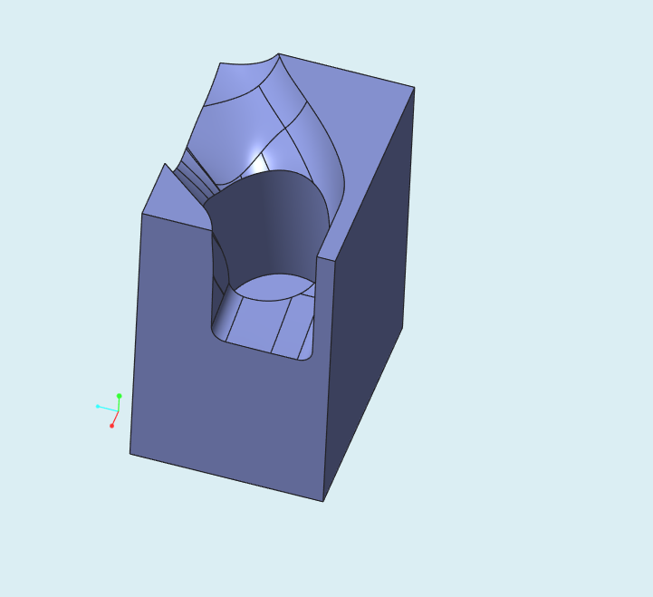
66 REPLIES 66
Oct 24, 2014
05:23 AM
- Mark as New
- Bookmark
- Subscribe
- Mute
- Subscribe to RSS Feed
- Permalink
- Notify Moderator
Please log in to access translation
Oct 24, 2014
05:23 AM
great work....wondering if duncan can show how he did it in NX
Oct 24, 2014
05:21 PM
- Mark as New
- Bookmark
- Subscribe
- Mute
- Subscribe to RSS Feed
- Permalink
- Notify Moderator
Please log in to access translation
Oct 24, 2014
05:21 PM
I tried, but for me I think the problem is getting good data from this Step file. If I use high accuracy model as a template, the incoming model has bunch of mangled surfaces.
Data comes as a solid in if I use a low accuracy model template, but it seems that soon after things go wrong because boundary blends don't work as the selected edges do not form valid loops, and projected curves end up with missing segments or little segments going back on themselves.
And trying to fix the data with the Import Data Doctor gave me a headache. So time to stop and have a weekend vacation away from Creo.
Oct 24, 2014
05:56 PM
- Mark as New
- Bookmark
- Subscribe
- Mute
- Subscribe to RSS Feed
- Permalink
- Notify Moderator
Please log in to access translation
Oct 24, 2014
05:56 PM
I think this is a no-win challenge in Creo. And you are right, the provided model is less than stellar.
The only thing that will work is to rebuilt the entire surface with sections and reference points for either a blend or boundary blend. You can use exisiting surface to characterize the new surface, but in general, I would try to make it independent. In IDD, separate out all the affected surfaces so they can easily be removed for the solidify process. Then determine the best way to rebuild the existing and missing geometry.
Blue... what is this feature?
Oct 25, 2014
01:43 PM
- Mark as New
- Bookmark
- Subscribe
- Mute
- Subscribe to RSS Feed
- Permalink
- Notify Moderator
Please log in to access translation
Oct 25, 2014
01:43 PM
Model with accuracy ~0.05 mm is simply a trash.
For manufacturing purposes it should be rebuilt from ground up. Moving it from software to software will just let it cause a never ending mess.
Anyway here is quick fix in Rhino.
Manufacturing it using RhinoCAM would do the job, but moving it to Creo and try to solidify it in say accuracy of 0.001? Not a good idea.
Oct 25, 2014
03:12 PM
- Mark as New
- Bookmark
- Subscribe
- Mute
- Subscribe to RSS Feed
- Permalink
- Notify Moderator
Please log in to access translation
Oct 25, 2014
03:12 PM
solidworks fill option has also failed.
....
Creo "remove" tool should be made more powerful...
ISDX surface also fails to do the job...
The geometry is very poor...
Curious to know how NX was able to do this...
Oct 25, 2014
03:17 PM
- Mark as New
- Bookmark
- Subscribe
- Mute
- Subscribe to RSS Feed
- Permalink
- Notify Moderator
Please log in to access translation
Oct 25, 2014
03:17 PM
Guessing!
Oct 27, 2014
03:16 AM
- Mark as New
- Bookmark
- Subscribe
- Mute
- Subscribe to RSS Feed
- Permalink
- Notify Moderator
Please log in to access translation
Oct 27, 2014
04:22 AM
- Mark as New
- Bookmark
- Subscribe
- Mute
- Subscribe to RSS Feed
- Permalink
- Notify Moderator
Please log in to access translation
Oct 27, 2014
04:22 AM
nice video...i think G0 is a free connection..so many places it is not tangent...right?
Oct 27, 2014
10:29 PM
- Mark as New
- Bookmark
- Subscribe
- Mute
- Subscribe to RSS Feed
- Permalink
- Notify Moderator
Please log in to access translation
Oct 27, 2014
10:29 PM
actually,the original geometry has something defects.Or it can be G1 connection.
Oct 27, 2014
12:30 PM
- Mark as New
- Bookmark
- Subscribe
- Mute
- Subscribe to RSS Feed
- Permalink
- Notify Moderator
Please log in to access translation
Oct 27, 2014
12:30 PM
Very impressive! Yes, Creo should be able to do this with a simple coundary blend. -Should-, being the operative term here.
Oct 27, 2014
10:52 PM
- Mark as New
- Bookmark
- Subscribe
- Mute
- Subscribe to RSS Feed
- Permalink
- Notify Moderator
Please log in to access translation
Oct 27, 2014
10:52 PM
As I know, the similar CAD system such as CATIA UG/NX Solidworks have the fill capability.But Creo...
Oct 28, 2014
12:58 AM
- Mark as New
- Bookmark
- Subscribe
- Mute
- Subscribe to RSS Feed
- Permalink
- Notify Moderator
Please log in to access translation
Oct 27, 2014
12:58 PM
- Mark as New
- Bookmark
- Subscribe
- Mute
- Subscribe to RSS Feed
- Permalink
- Notify Moderator
Please log in to access translation
Oct 27, 2014
12:58 PM
done in solidworks 2012
Oct 28, 2014
04:16 PM
- Mark as New
- Bookmark
- Subscribe
- Mute
- Subscribe to RSS Feed
- Permalink
- Notify Moderator
Please log in to access translation
Oct 28, 2014
04:16 PM
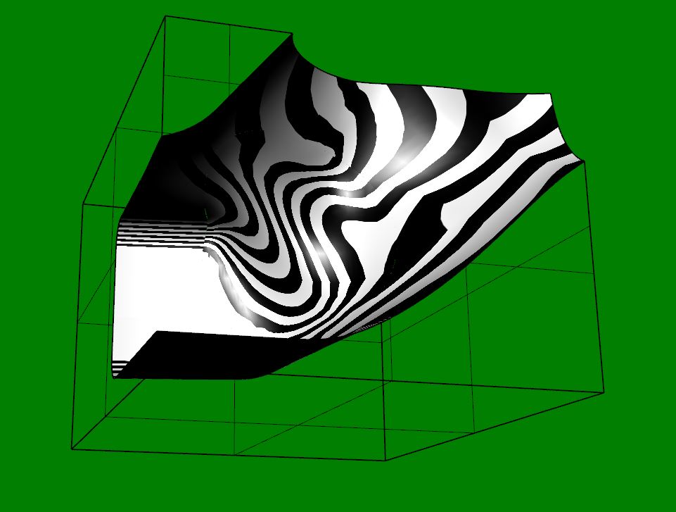
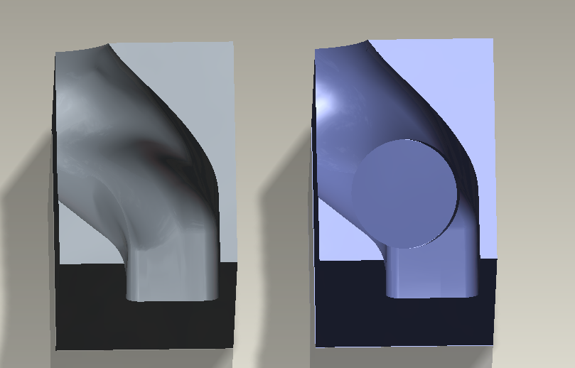
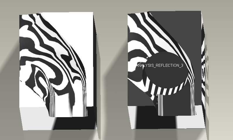
I can't open native Solidworks file, but i performed a reflection analysis on STEP coming from Solidworks. It's ok. Just a zone with no tangency but i think it could coming from STEP conversion. It seems that solidworks and nx manage surfaces with no respect of patches of near surfaces. And that's good.
Oct 28, 2014
04:32 PM
- Mark as New
- Bookmark
- Subscribe
- Mute
- Subscribe to RSS Feed
- Permalink
- Notify Moderator
Please log in to access translation
Oct 28, 2014
04:32 PM
This should be highly embarrassing to PTC! 
Oct 28, 2014
05:30 PM
- Mark as New
- Bookmark
- Subscribe
- Mute
- Subscribe to RSS Feed
- Permalink
- Notify Moderator
Please log in to access translation
Oct 28, 2014
05:30 PM
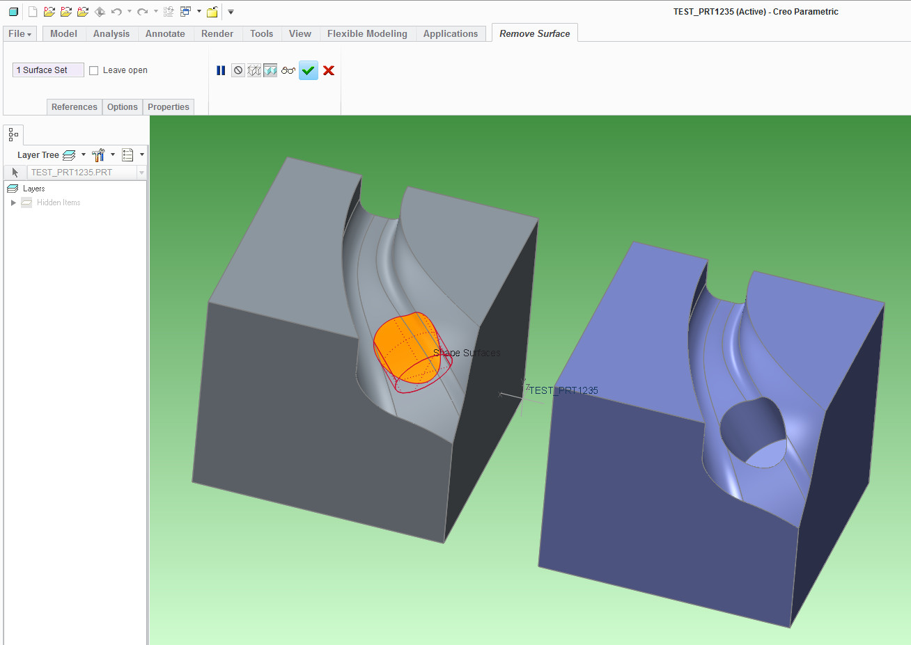
Yes, it seems Creo is pretty weak with dealing with bad data. I've made a pretend model that mimics what the OP was trying to do.
Funny thing is, the software is quite capable of dealing with such holes if you are working with native data.
You can use flexible modeling "remove" feature to fill in holes like these very easily.
Another way is to copy and paste the surfaces and use the "fill holes" option.
Here's where things go bad: After exporting the model to STEP format and then bringing the data back into a fresh session, the IDD reports that model has bad vertices!
Now the copy surface and fill holes option no longer works.
But, as shown in the image above, the flexible modeling "remove" method still works.
So maybe there's hope but only if your geometry doesn't have big errors (and how often does that happen ?  )
)
Oct 28, 2014
11:54 PM
- Mark as New
- Bookmark
- Subscribe
- Mute
- Subscribe to RSS Feed
- Permalink
- Notify Moderator
Please log in to access translation
Oct 28, 2014
11:54 PM
we so much want..that CREO should be the best software..but i think...PTC does not share the same vision?
Oct 29, 2014
12:00 AM
- Mark as New
- Bookmark
- Subscribe
- Mute
- Subscribe to RSS Feed
- Permalink
- Notify Moderator
Please log in to access translation
Oct 29, 2014
12:00 AM
I think PTC should give this challenge to their R&D quys logging exactly how long it takes them to figure this out.
And their performance should be part of rating their their next review.
And if it requires the advanced surface extension, knowing it can do an adequate job in SolidWorks... maybe the advanced module should be included with core Creo.
Oct 29, 2014
12:07 AM
- Mark as New
- Bookmark
- Subscribe
- Mute
- Subscribe to RSS Feed
- Permalink
- Notify Moderator
Please log in to access translation
Oct 29, 2014
12:07 AM
the ISDX surface option does not work with non-tangent edges
Oct 29, 2014
12:44 AM
- Mark as New
- Bookmark
- Subscribe
- Mute
- Subscribe to RSS Feed
- Permalink
- Notify Moderator
Please log in to access translation
Oct 29, 2014
12:44 AM
Does PTC cover up their shortage?
Oct 29, 2014
01:10 AM
- Mark as New
- Bookmark
- Subscribe
- Mute
- Subscribe to RSS Feed
- Permalink
- Notify Moderator
Please log in to access translation
Oct 29, 2014
01:10 AM
only PTC can answer this i guess..
Oct 29, 2014
04:19 AM
- Mark as New
- Bookmark
- Subscribe
- Mute
- Subscribe to RSS Feed
- Permalink
- Notify Moderator
Please log in to access translation
Oct 29, 2014
04:19 AM
+1
Not that I believe it has gonna have any impact anytime soon, but can anyone be bothered to post this in the ideas section?
I'm sure there is more than just a handfull of us who would like to tell PTC what is the real meaning of "AnyData Adoption".
http://creo.ptc.com/2010/10/27/any-data-adoption/
Let me also bring up the terms "Unite Technology", and "Flexible Modeling". Though, these are the bells and whistles we are not gonna be able to use on some (or maybe most) occasions, just because of the way Creo treats the input data.
I guess you realize it doesn't have to be only STEP or IGES data coming in. It can be data from say Catia directly, which Creo Parametric treats in alot worse manner than STEP data during the import, meaning it introduces alot more bad geom, gaps, etc.
http://creo.ptc.com/2014/07/28/ptc-creo-fmx-and-unite-technology-better-together/
STEP, IGES or any universal data format type is just a middle man in the process of data transfer. It's an unnecesarry copy of the geometry, that serves only as a link between all of the CAD/CAM systems out there. For PTC to eliminate this link out of the process they will have to make sure the software can easily deal with data such as posted by the OP (Blue).
Regards,
~J
Oct 29, 2014
03:34 AM
- Mark as New
- Bookmark
- Subscribe
- Mute
- Subscribe to RSS Feed
- Permalink
- Notify Moderator
Please log in to access translation
Oct 29, 2014
03:34 AM
ok this one is in creo 2.0..step file attched as i hace student edition
Oct 29, 2014
12:23 PM
- Mark as New
- Bookmark
- Subscribe
- Mute
- Subscribe to RSS Feed
- Permalink
- Notify Moderator
Please log in to access translation
Oct 29, 2014
12:23 PM
Rohit, this is easier to do, yes, but nowhere near industrial-design-guy-proof...
Oct 29, 2014
11:49 PM
- Mark as New
- Bookmark
- Subscribe
- Mute
- Subscribe to RSS Feed
- Permalink
- Notify Moderator
Please log in to access translation
Oct 29, 2014
11:49 PM
could you please explain me further?
Oct 30, 2014
02:20 AM
- Mark as New
- Bookmark
- Subscribe
- Mute
- Subscribe to RSS Feed
- Permalink
- Notify Moderator
Please log in to access translation
Oct 30, 2014
02:20 AM
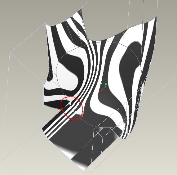
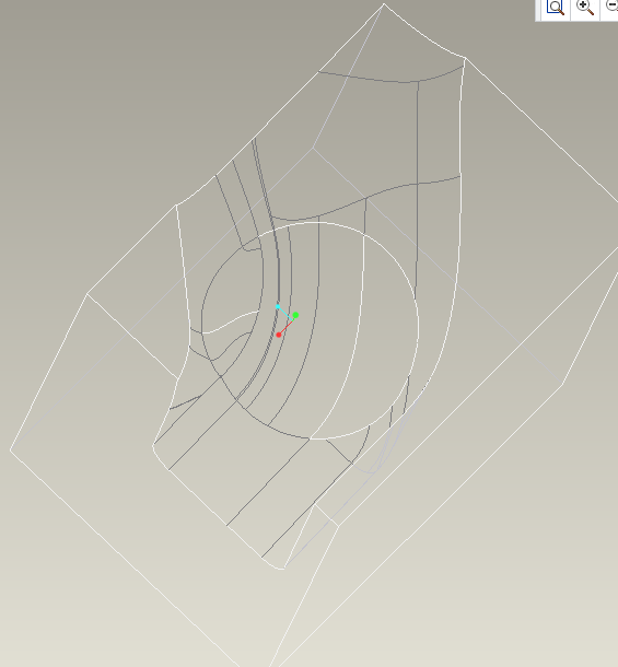
There's no complete tangency on Rohit's step. No hidden visualization with white edges shows no tangency edges. I improved a little with IDD, but that tool can't force tangency anywhere. Anyway to repair a 3D file is good. For manufacturing no.
Oct 29, 2014
11:54 PM
- Mark as New
- Bookmark
- Subscribe
- Mute
- Subscribe to RSS Feed
- Permalink
- Notify Moderator
Please log in to access translation
Oct 29, 2014
11:54 PM
NICE
Oct 26, 2014
06:26 PM
- Mark as New
- Bookmark
- Subscribe
- Mute
- Subscribe to RSS Feed
- Permalink
- Notify Moderator
Please log in to access translation
Oct 26, 2014
06:26 PM
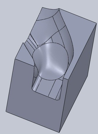
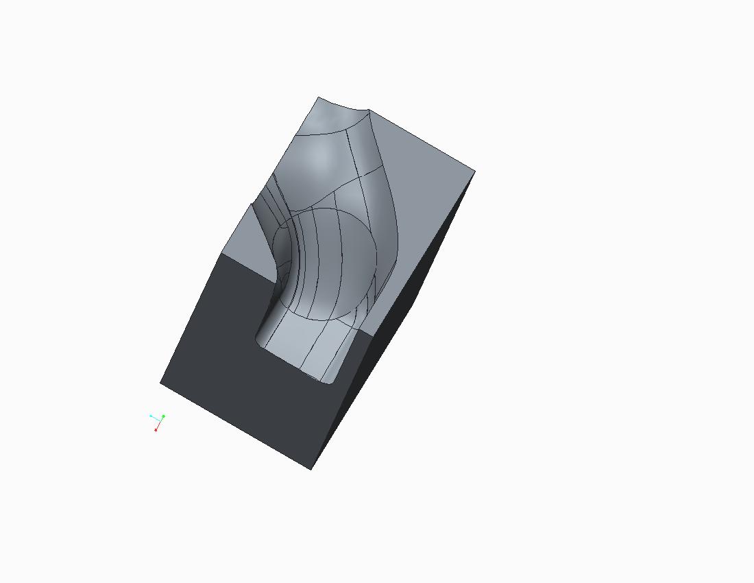
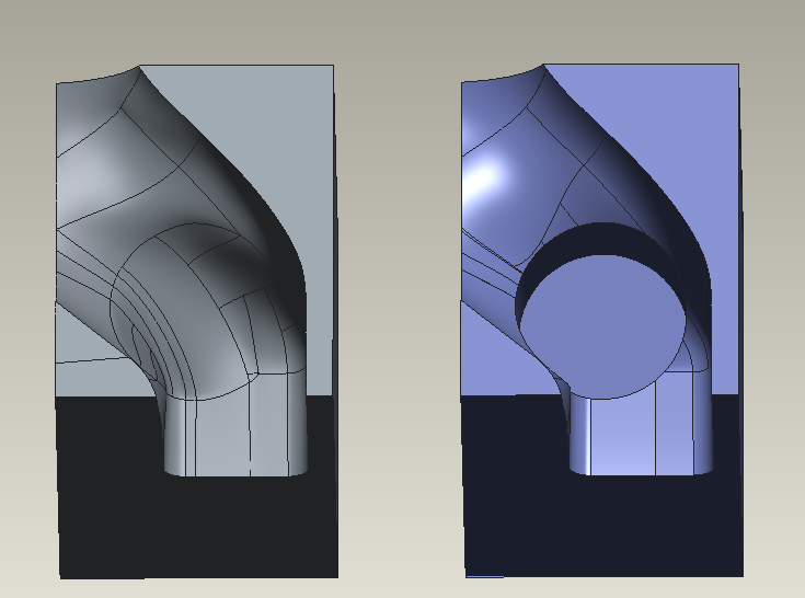
I have no excellent skills in ISDX module, but i reach a complete filling of entire surface with tangency continuity. I rebuild surfaces. Expecially near the hole, geometry was very poor. IDD isn't a perfect solution. I think that for guys of reverse enginering filling this hole is a joke. Sure it's not a 2 click work as in other software. I attach Creo2 and STEP file. There are little distorsions on my work, but i'm not a specialist.
Oct 29, 2014
10:18 AM
- Mark as New
- Bookmark
- Subscribe
- Mute
- Subscribe to RSS Feed
- Permalink
- Notify Moderator
Please log in to access translation
Oct 29, 2014
10:18 AM
Solidworks and NX both use Parasolid Kernel, maybe this is a limitation of Granite?
Oct 30, 2014
01:08 AM
- Mark as New
- Bookmark
- Subscribe
- Mute
- Subscribe to RSS Feed
- Permalink
- Notify Moderator
Please log in to access translation
Oct 30, 2014
01:08 AM
I don't think so,In advanced surface,Creo is weak compared with NX.Creo just provide IDD TOOL to fix input data(igs/step).It's a limited capabilities tool. From Proe to Creo ,do you see the advanced surface be enhanced?
