
Turn on suggestions
Auto-suggest helps you quickly narrow down your search results by suggesting possible matches as you type.
Showing results for
Please log in to access translation
Turn on suggestions
Auto-suggest helps you quickly narrow down your search results by suggesting possible matches as you type.
Showing results for
Community Tip - Want the oppurtunity to discuss enhancements to PTC products? Join a working group! X
- Community
- Creo+ and Creo Parametric
- Customization
- DXF exporting of formats causing issues...
Translate the entire conversation x
Please log in to access translation
Options
- Subscribe to RSS Feed
- Mark Topic as New
- Mark Topic as Read
- Float this Topic for Current User
- Bookmark
- Subscribe
- Mute
- Printer Friendly Page
DXF exporting of formats causing issues...
Jun 07, 2011
12:22 PM
- Mark as New
- Bookmark
- Subscribe
- Mute
- Subscribe to RSS Feed
- Permalink
- Notify Moderator
Please log in to access translation
Jun 07, 2011
12:22 PM
DXF exporting of formats causing issues...
We have a "special" format here that we use for exporting our DXF files from. That format is basically blank, except for one important / critical piece of information: the revision letter of the part. Up until now, this hasn't really been a big deal for the ME guys that do our pathing, because they had to manually touch every part , so deleting this revision block , wasn't a huge deal. But, we've now gotten some new laser pathing software that allows us to go straight from DXF file to G-CODE with no interaction. Obviously, if we could get this working it would save us a TON of time.
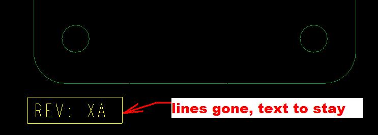
When our rep (Amada, not PTC) showed us this, he suggested that we simply punt the revision code. That's not really a good deal, because even though it would be automated, if we ever DID want to verify which version the DXF was, we would no longer have that information. The second suggestion then, was to put the revision information onto a layer, and then he would just block that layer for the automation part of things, and we could still see it if needed .I didn't think at the time that this was doable in a FORMAT, and I have since verified that I can't figure out how to put this revision code on a layer IN THE FORMAT.A nd it has to be in the format, becasue that's the part that we want to be able to add to this sheet to setup all of the parameters, etc. Then, we find out that the software can automatically "reject" pure text, if it's pure text. That works good, but the problem there is that the revision letter MUST be in a table to show up as a parameter on the titleblock, so it has lines around it. The text would / could go away ,but the lines surrounding the table would still be there.
So, I've gotten it down to the following bits:
I want / need the information in this TABLE to show up, but I don't want the outside table lines. I have tried blanking these lines, and I can't get them to blank, because you can only blank internal lines. I have tried adding the parameter in this case, &REVISION_LETTER to the format just as text/ note, and that doesn't work either, because with tables, the only way that parameters work is if they are in a table, so I'm back to the point that I need to have the table lines blanked.
Does anyone know of a way that I might be able to do this? Am I missing something on putting this information on a layer that I can turn off (that would solve the problem as well)? Is there a way to blank these outside table lines, OR put all tables onto a table layer?, which may or may not work, because this table is in the FORMAT, and not on the drawing.
I am so close to having something totally automated, and one little fly in the ointment is preventing that, and this seems so simple, that there HAS to be something that I'm missing, but I can't figure out what that something is ...
WF5 - M070
This thread is inactive and closed by the PTC Community Management Team. If you would like to provide a reply and re-open this thread, please notify the moderator and reference the thread. You may also use "Start a topic" button to ask a new question. Please be sure to include what version of the PTC product you are using so another community member knowledgeable about your version may be able to assist.
1 REPLY 1
Jun 07, 2011
03:49 PM
- Mark as New
- Bookmark
- Subscribe
- Mute
- Subscribe to RSS Feed
- Permalink
- Notify Moderator
Please log in to access translation
Jun 07, 2011
03:49 PM
I received several responses to this, THANKS ALL!
But the one that finally makes sense, is to create an automatic layer (rules based layer) that adds ALL tables to it. Now that I have a layer that contains all of the tables on a drawing, I'll be able to export the drawing with tables on a set layer. Our laser pathing software, then, will cue off of this layer name, and turn those items off automatically, and they will not be brought over as part of the G-CODE creation. But that information will still be there if we want to verify that via the DXF if we cut the right information.
One thing that I had forgotten about layer creation, that's worth mentioning here, is that it's important to check the ASSOCIATIVE button:
...when creating layers in which you want EVERYTHING to be added to the layer, regardless of where it was created in the drawing.
Thanks Mark! for helping me with this, and helping me find a solution!!!
Announcements


Top Tags
