
Turn on suggestions
Auto-suggest helps you quickly narrow down your search results by suggesting possible matches as you type.
Showing results for
Please log in to access translation
Turn on suggestions
Auto-suggest helps you quickly narrow down your search results by suggesting possible matches as you type.
Showing results for
Community Tip - New to the community? Learn how to post a question and get help from PTC and industry experts! X
- Community
- Creo+ and Creo Parametric
- Manufacturing (CAM)
- Re: Any one else seeing more toolpath errors?
Translate the entire conversation x
Please log in to access translation
Options
- Subscribe to RSS Feed
- Mark Topic as New
- Mark Topic as Read
- Float this Topic for Current User
- Bookmark
- Subscribe
- Mute
- Printer Friendly Page
Any one else seeing more toolpath errors?
Dec 01, 2011
10:48 AM
- Mark as New
- Bookmark
- Subscribe
- Mute
- Subscribe to RSS Feed
- Permalink
- Notify Moderator
Please log in to access translation
Dec 01, 2011
10:48 AM
Any one else seeing more toolpath errors?
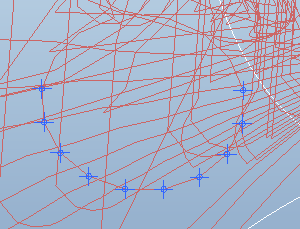
I have been finding more and more gouges lately and i am wondering if any one else has been finding the same. MAINTAIN_CUT_TYPE will generate these strange circular gouges.
This thread is inactive and closed by the PTC Community Management Team. If you would like to provide a reply and re-open this thread, please notify the moderator and reference the thread. You may also use "Start a topic" button to ask a new question. Please be sure to include what version of the PTC product you are using so another community member knowledgeable about your version may be able to assist.
Labels:
- Labels:
-
General
18 REPLIES 18
Dec 02, 2011
05:47 PM
- Mark as New
- Bookmark
- Subscribe
- Mute
- Subscribe to RSS Feed
- Permalink
- Notify Moderator
Please log in to access translation
Dec 02, 2011
05:47 PM
Sorry to say this but I have never used Maintain_Cut_Type. What strategy is that in the picture?
Dec 05, 2011
10:44 AM
- Mark as New
- Bookmark
- Subscribe
- Mute
- Subscribe to RSS Feed
- Permalink
- Notify Moderator
Please log in to access translation
Dec 05, 2011
10:44 AM
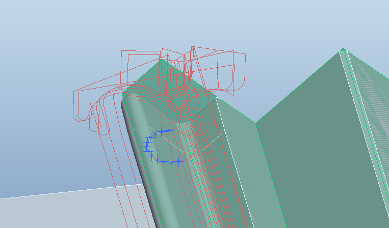
The picture is from a roughing cycle
Dec 05, 2011
01:12 PM
- Mark as New
- Bookmark
- Subscribe
- Mute
- Subscribe to RSS Feed
- Permalink
- Notify Moderator
Please log in to access translation
Dec 05, 2011
01:12 PM
What release are you using? I have seen similar output. We have also ran into an issue where the tool path will reverse the cut direction midway thru a cavity. Support says the issue has been resolved in Wildfire 5.0 M120 which is due out the end of December.
Dec 05, 2011
02:05 PM
- Mark as New
- Bookmark
- Subscribe
- Mute
- Subscribe to RSS Feed
- Permalink
- Notify Moderator
Please log in to access translation
Dec 05, 2011
02:05 PM
WF5 M100 but I have seen this circular error happen since wildfire 3 it just seems to be happening with much more frequency now. I'm to the point where I avoid using this cut type at the cost of cycle time.
Dec 06, 2011
08:53 AM
- Mark as New
- Bookmark
- Subscribe
- Mute
- Subscribe to RSS Feed
- Permalink
- Notify Moderator
Please log in to access translation
Dec 06, 2011
08:53 AM
Wow... gouging with roughing is a serious problem. If you leave more stock will the gouges go away?
I don't use maintain cut type so I have never seen this. I try and use the constant load for roughing
Dec 06, 2011
02:53 PM
- Mark as New
- Bookmark
- Subscribe
- Mute
- Subscribe to RSS Feed
- Permalink
- Notify Moderator
Please log in to access translation
Dec 06, 2011
02:53 PM
Found another one today!
Dec 20, 2011
07:44 AM
- Mark as New
- Bookmark
- Subscribe
- Mute
- Subscribe to RSS Feed
- Permalink
- Notify Moderator
Please log in to access translation
Dec 20, 2011
07:44 AM
Here is a roughing error for you Nick!! Why do they always seem to be round. Software must be confused and running in circles!
Dec 20, 2011
09:17 AM
- Mark as New
- Bookmark
- Subscribe
- Mute
- Subscribe to RSS Feed
- Permalink
- Notify Moderator
Please log in to access translation
Dec 20, 2011
09:17 AM
yes I like that one! it is always circles have you noticed that adjusting the step over can effect these errors?
Dec 21, 2011
01:21 PM
- Mark as New
- Bookmark
- Subscribe
- Mute
- Subscribe to RSS Feed
- Permalink
- Notify Moderator
Please log in to access translation
Dec 21, 2011
01:21 PM
Nick and Brian:
Just to make sure we're all in the same page: Was the problem formally reported to PTC? Did you get an SPR?
I'm assuming that the problem is not the same for both...
This seems critical and sometimes we think someone reported a problem but nobody did, so PTC don't fix it... I'm struggling with a problem when reversing cut direction and lead in / lead outs getting messed.. never reported because it as a very known flaw...I thought other people have done it... so, just in case...
Dec 21, 2011
01:40 PM
- Mark as New
- Bookmark
- Subscribe
- Mute
- Subscribe to RSS Feed
- Permalink
- Notify Moderator
Please log in to access translation
Dec 21, 2011
01:40 PM
There was an SPR filed on our issue. It is corrected in M120, which is due out later this month.
I usually make it a habit of reporting any issue we come across. Even though dealing with tech support leaves something to be desired these days.
Dec 21, 2011
01:50 PM
- Mark as New
- Bookmark
- Subscribe
- Mute
- Subscribe to RSS Feed
- Permalink
- Notify Moderator
Please log in to access translation
Dec 21, 2011
01:50 PM
We're also very active in reporting problems and pushing for fixes... this software is damn powerful but some bugs should not be there after so many years...
It's not so buggy like Mastercam but it can kick your ass from time to time... 
Our company alone got nearly 16 bugs fixes in NC in the past year...
So, keep reporting and the product will get better... I hope 
Thanks for the prompt reply,
Daniel
Jan 09, 2012
07:35 AM
- Mark as New
- Bookmark
- Subscribe
- Mute
- Subscribe to RSS Feed
- Permalink
- Notify Moderator
Please log in to access translation
Jan 09, 2012
07:35 AM
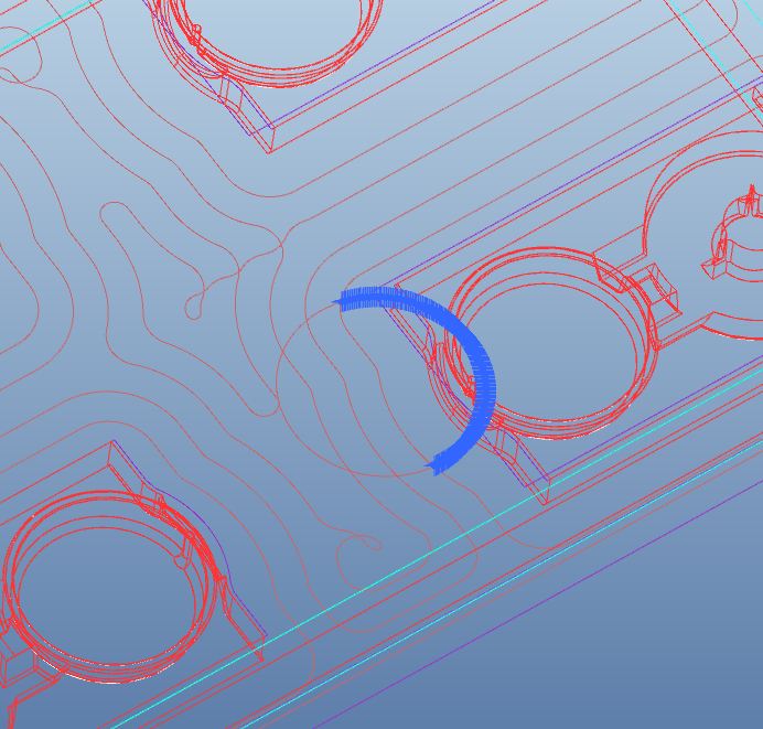
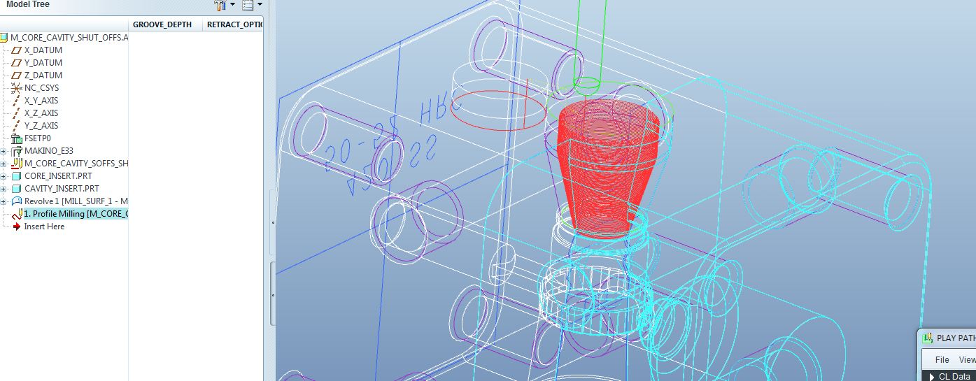
How about an error while profile milling while we are on toolpath errors!!
I do a lot of profile milling. Look at what I have been getting lately. I built a revolved mill surface for the profile cut then select that mill surface for the profile sequence. for some reason after making several correct passes it makes a pass outside the surface in another cut for no apparent reason!! WTF!! this stuff is really starting to bother me.Tired of trying to make good parts, But spending WAAAAY too much time trying to diagnose tool path errors on stuff in previous revs I could do without even thinking about.
Jan 20, 2012
10:55 AM
- Mark as New
- Bookmark
- Subscribe
- Mute
- Subscribe to RSS Feed
- Permalink
- Notify Moderator
Please log in to access translation
Jan 20, 2012
10:55 AM
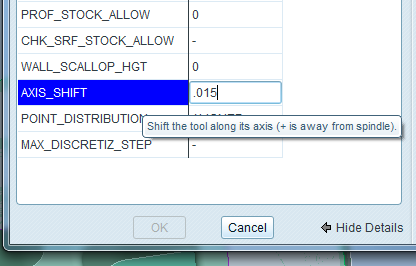
I have a question regarding profile milling. Thought i would ask because you said you do it alot. I want to sometimes do a profile around something and leave say .015" onthe the bottom of the part say so that the part won't break through the vacuum that is applied. I know if WF4 I could adjust a "Z offest) parameter which no longer exsists in WF5 NC. Do you or anyone have a way to do this in WF5 Pro\NC?
Jeff
Jan 20, 2012
11:01 AM
- Mark as New
- Bookmark
- Subscribe
- Mute
- Subscribe to RSS Feed
- Permalink
- Notify Moderator
Please log in to access translation
Jan 20, 2012
11:01 AM
AXIS_SHIFT
Jan 20, 2012
11:04 AM
- Mark as New
- Bookmark
- Subscribe
- Mute
- Subscribe to RSS Feed
- Permalink
- Notify Moderator
Please log in to access translation
Jan 20, 2012
11:04 AM
Awsome!!! Thanks
Jan 20, 2012
12:57 PM
- Mark as New
- Bookmark
- Subscribe
- Mute
- Subscribe to RSS Feed
- Permalink
- Notify Moderator
Please log in to access translation
Jan 20, 2012
12:57 PM
Jeff,
What Nick said is correct. Use axis shift. You just need to be carefull.Take care with the note that nick has displayed (shift the tool along it's axis (+ is away from the spindle)). SO in order for you to leave stock on the bottom of the profile you want a negative number in the axis shift. Also the axis shift shifts the whole profile by the amount you enter. so if you have 5 profile passes around your part stepping down to your Z depth all the passes will be shifted by the amount in axis shift. usually not a big deal but that's what happens.
Good luck.
Jan 20, 2012
02:57 PM
- Mark as New
- Bookmark
- Subscribe
- Mute
- Subscribe to RSS Feed
- Permalink
- Notify Moderator
Please log in to access translation
Jan 20, 2012
02:57 PM
Great thanks!! Works the same as WF4 i guess only name changed for "Z offset" I believe. Does someone know if or how to update the pro/nc like talked about in the above posts?
Jan 20, 2012
04:06 PM
- Mark as New
- Bookmark
- Subscribe
- Mute
- Subscribe to RSS Feed
- Permalink
- Notify Moderator
Please log in to access translation
Jan 20, 2012
04:06 PM
I’m having problems with “Customizing” some cuts like Engraving and Auxiliary sequences.
Windows says the Creo is not responding and need to close the program.
This may be simalar to Case 2107567
Creo 1.0 M020
Announcements


Top Tags
