Community Tip - You can Bookmark boards, posts or articles that you'd like to access again easily! X
- Community
- Creo+ and Creo Parametric
- Manufacturing (CAM)
- Re: Creo NC work center relation parameters
- Subscribe to RSS Feed
- Mark Topic as New
- Mark Topic as Read
- Float this Topic for Current User
- Bookmark
- Subscribe
- Mute
- Printer Friendly Page
Creo NC work center relation parameters
- Mark as New
- Bookmark
- Subscribe
- Mute
- Subscribe to RSS Feed
- Permalink
- Notify Moderator
Creo NC work center relation parameters
For whatever reason, Creo does not offer the ability to set a default clearance distance per machine. I do not always remember all the travels on our machines and would like to set default clearance values to solve that issue.
I basically want to set a relation that states:
IF work cell = "insert machine name"
clearance = XX.XX
However to do this, I need to know the parameter names to pull for the work center and the clearance, and I do not know them. Does anyone know what those parameters are, or know a better way to do this?
Solved! Go to Solution.
Accepted Solutions
- Mark as New
- Bookmark
- Subscribe
- Mute
- Subscribe to RSS Feed
- Permalink
- Notify Moderator
This is the answer to your question directly from PTC.
Answer:
Resolution
Not part of the Creo Parametric functionality
There is no operation parameter with the name of a Workcell used
https://www.ptc.com/en/support/article/CS133428?source=search&source=copyurl
- Mark as New
- Bookmark
- Subscribe
- Mute
- Subscribe to RSS Feed
- Permalink
- Notify Moderator
I do not know of a way to reference a feature name in a relation.
Do you want the retract plane location (dimensional value) to change based upon the active workcell?
or
Do you want the default NC Sequence parameter CLEAR_DIST to be adjusted based upon active workcell?
You might consider a workflow where you have a different startpart for each machine with this set the way you want it, you would select the machine (startpart) for each job prior to programming.
-Bryant-
- Mark as New
- Bookmark
- Subscribe
- Mute
- Subscribe to RSS Feed
- Permalink
- Notify Moderator
Hey Bryan,
Yes, I am wanting to have the retract plane dimension change based on the selected workcell.
I am not sure if I know exactly what a start part is.
- Mark as New
- Bookmark
- Subscribe
- Mute
- Subscribe to RSS Feed
- Permalink
- Notify Moderator
You can set your config.pro to look at a specific directory you setup to contain “startparts” using option mfg_start_model_dir – this directory could have multiple manufacturing files (perhaps one for each machine or machine type) and you would select which one to use when you create a new manufacturing file. Config option template_mfgnc will allow you to select which manufacturing file will be your default.
I find startparts to be very powerful, I choose this workflow to address the differences between machine tools, each startpart can contain some or all of the following:
Coordinate system, datum planes, points Named views Workcells With active SITE files Post processor # defined Operations With predefined retract plane Geometry: Surfaces, copy geom, publish geom Cutting tools loaded into workcell – could align with shop standardized tooling Workpiece NC Sequences Which can be copied/pasted quickly and could contain custom relations/parameters Associated drawing files – to generate setup sheets Annotation elements – for reference Drill tap chart, etc. Fixture representations- Mark as New
- Bookmark
- Subscribe
- Mute
- Subscribe to RSS Feed
- Permalink
- Notify Moderator
Awesome. I've been doing this manually. This is so much better!
- Mark as New
- Bookmark
- Subscribe
- Mute
- Subscribe to RSS Feed
- Permalink
- Notify Moderator
Thank you for your very detailed response.
The issue that I see with using this for our workflow, would be losing the ability to easily post out code for another machine when the need rises. It's not uncommon for a machine to go down, and then we need to move the job to another machine. With our current workflow we are able to open the parts manufacturing model, change to whatever workcenter that we want to move it to, and then code it out.
If I am understanding correctly, with your workflow, to move it to another machine would require that machine having its own part manufacturing model as well, meaning multiple models for the same part to have it on different machines?
- Mark as New
- Bookmark
- Subscribe
- Mute
- Subscribe to RSS Feed
- Permalink
- Notify Moderator
It really depends on how drastic the change is and how different your machines are – we aren’t going from a mill to a lathe.
We use the same startpart for 3 to 5axis Haas mills and for a 5 axis horizontal boring mill but each of the 3 use different post processors (the number is defined in the workcenter). We normally have an idea where the part is headed when we begin programming so we have some mapkeys to make the basic adjustments and we avoid using 5 axis toolpaths for a 3 axis mill job.
What is changes between your workcenters?
You might consider a single manufacturing assembly startpart that contains all your workcenters, then you might be able to redefine which work center is being referenced by your operation?
-Bryant-
- Mark as New
- Bookmark
- Subscribe
- Mute
- Subscribe to RSS Feed
- Permalink
- Notify Moderator
All of our workcenters are mills, and each have their own posts. Maybe I wasn't clear in my original question, but we do have a single manufacturing start model that we use when making a new part (I guess I just never heard it called start part). This way if we want to move the part to a new machine, we just change the workcenter it is on, (which each workcenter has its own post) and repost.the file. This allows us to have one part model, that has all the machines inside the model, and you just select the workcenter that you would like to machine the part on, and recode.
This circles us back around to my initial question on trying to figure out how I can set my default clearance based upon which workcenter is selected in Creo?
- Mark as New
- Bookmark
- Subscribe
- Mute
- Subscribe to RSS Feed
- Permalink
- Notify Moderator
You can use the postprocessors and not the built in machine.
Inside the PP you set the parameters.
You can give it out with step by step, but the first PP calls the second machine. And the second oculd call the third.
All with different spindle speeds for instance.
P.S.: Is there a way to automate the generatoin of the NCL and PP Files with one click?
I know you can give out all out sequences merged to one CL-file with using the operation or a set, but we give out every sequence on its own.
It would be nice if we could put out all sequences, i.e. 1_xx, 2_xx and so on with one command/click.
- Mark as New
- Bookmark
- Subscribe
- Mute
- Subscribe to RSS Feed
- Permalink
- Notify Moderator
Thats interesting, and I did not know that you could do that.
But I don't think that would help with me trying to set my clearance on a per machine basis?
- Mark as New
- Bookmark
- Subscribe
- Mute
- Subscribe to RSS Feed
- Permalink
- Notify Moderator
Unfotunately you are right - I searched for many ways but it is not possible to find out the parameter!
And in the machine configuration, there is no option.
Again - it would be very helpful to have a full list of parameter and how to access those variables.
- Mark as New
- Bookmark
- Subscribe
- Mute
- Subscribe to RSS Feed
- Permalink
- Notify Moderator
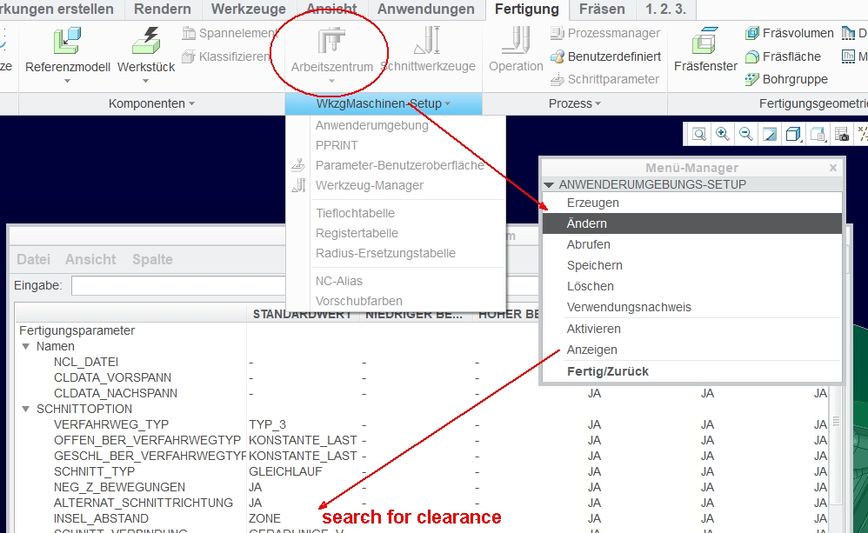
What you CAN do, is generate a XML Template:
So you set the desired value in the operation, right click on it and save as a template.
You make one for each machine. Then, you load that template with the way shown in the second picture.
That is the best help I can give you.
Export after filling in the params.
Load the XML Template
P.S.: If you look in the xml template, ther are interesting values... but.. I found no way to use them within creo..
- Mark as New
- Bookmark
- Subscribe
- Mute
- Subscribe to RSS Feed
- Permalink
- Notify Moderator
It would be a great help for anybody in every situation to have a list of ALL parameters in Creo NC.
I would love to have access to the sequence number but how do I manage this? What is the name of the parameter?
In your case maybe it helps you because then it is set as a standard or you select which set of the setups you use.
- Mark as New
- Bookmark
- Subscribe
- Mute
- Subscribe to RSS Feed
- Permalink
- Notify Moderator
Do you mean a list of all sequence level parameters? Attached is an excel list I compiled by outputting SITE files for each type workcell and combining.
- Mark as New
- Bookmark
- Subscribe
- Mute
- Subscribe to RSS Feed
- Permalink
- Notify Moderator
Thank you for that list and your quick response!
The first paragraph I wrote was concerning my problem when outputting CL_Data,
I have no idea where to get the param that gives me the STEP NO'# for each step.
I just get the Name, not the Step Number.
The second paragraph with the picture I made, addresses the question of the threadstarter.
Now the list you made is about the parameters for the machining/process,for creating that step and the calculation of the path.
What I look for, is laying "above" that parameter of the step, it is the naming and output of the cl_file. I can access very much through the Process Manager, but also there I am searching and searching for an answer, Please have a look at my two screenshots concerning this problem.
Maybe this forum helps, but there were others that asked and never got an answer to this..
Like in this thread: Parameter Sequence Number
It is old and locked, but also dewscribes my problem pretty well.
Right now I use a workaround and manually put in the "_1" and so on, so the name is taken from the project. But even this equation is not saved as a parameter when I save that for another project. Equations are not handed over - another thing I have not found out.
Another thing is, when I make a documentation, the sequence number is inserted. So somehow this is sure accessible, but it is not documented.
Ot there is a .pro parameter, that gives the NCL Naming a sequence number right from the start. But I want to give the sequence the same name and not i.e. for sequence number 1: "Schruppen_VS_D32".
I want the name to be OS_1842_NC_01 or 01_OS_1842_NC.
Look at the third pic, it is from the report that is generated.
Pic1
Pic2
Pic3
- Mark as New
- Bookmark
- Subscribe
- Mute
- Subscribe to RSS Feed
- Permalink
- Notify Moderator
I agree that it would be nice to have access to all these parameters for use in relations, I find myself doing too much administrative work like naming sequences, etc. – unfortunately I have not figured out how to do it, here are some thoughts, nuances and anomalies perhaps something might spark an idea:
- If you extract toolpaths from a part (a part that has embedded mfg annotation elements) they come in with a number sequencing similar to what you want
- If you insert a design UDF multiple times in a file it will sequence the name of the group
- I do not know of a way to define a relation that will control the name of features in the model tree
- Pro/ReportI do not know how to access all the parameters you can access in drawing mode while in your manufacturing assembly – mfg.actoper.step for instance
- I notice that there is a feature level parameter named “description” in newly generated toolpaths that automatically gets sequenced but it is a parameter type = note and I have been unable to reference it to drive a string type parameter
- The value of description is static and does not update if sequence is reordered in model tree
- If you save out an XML template of NC sequence and look at the parameters, many parameters that exist, it seems those that start with “PRO_E_” are not accessible via the relations editor - PRO_E_NCSEQ_TYPE for instance
- POCKET_NUMBER is an interesting parameter, it is a great parameter to add to your model tree
- it is a read only type parameter
- it does not exist in the NC sequence parameter list
- TOOL POSITION is the column in the tool manager which correlates to this POCKET_NUMBER
- This value is driven by the TOOL NUMBER field of a tools definition on the Settings tab
- PRO_E_MFG_TOOL_REF_POCKET is a parameter in the XML template but not accessible at NC feature level
- There seem to be parameters that are visible in model tree but not via relation editor, you can add a column to model tree Feat Type for instance but how do you access this value via relations editor?
- The number of parameters from a (5 axis milling) manufacturing file varies greatly depending upon the method/type but I believe all are types of parameters
- Operation XML output = 775
- If you add every column possible to process manager = 765
- All SITE file parameters = 609
- All mfg model tree columns = 631
- All PPRINT parameters = 79
- Within the process manager if you use the global relations editor you can create a relation like PULLOUT_DIST = 0 and once you exit the process manager this relation will exist in all the NC sequences in model tree – quick way to do a mass edit
- If in relations editor for an NC Sequence you can reference MACHINING_DISTANCE as a parameter even though this is not an NC sequence parameter and not a feature parameter
- Mark as New
- Bookmark
- Subscribe
- Mute
- Subscribe to RSS Feed
- Permalink
- Notify Moderator
Thank you very much, This is very helpful.
I will need time to use this knowledge.
But there are Parameters that start with the "PRO_E_MFG" Name. So it is all try and error (the fastest to test is within the Expression Check:
So I can say
PTC_MFG_PRM_CL_FILE = rel_model_name+"_01"
and that works fine.
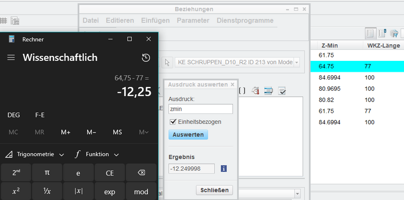
You can also, and that nags me, use ZMIN to show how deep the tool goes down o fthe Workpiece Coordinate System.
UNofrtunately again, it can not be shown inside the process manager.
To get there what ZMIN already knows, I have to calculate Z Minimum - "The length of the workpice in Z-direction"
to get the desired result.
But how to put that ZMIN into the report?
How can I set local parameters for every sequence with one command? 🙂
You wrote:
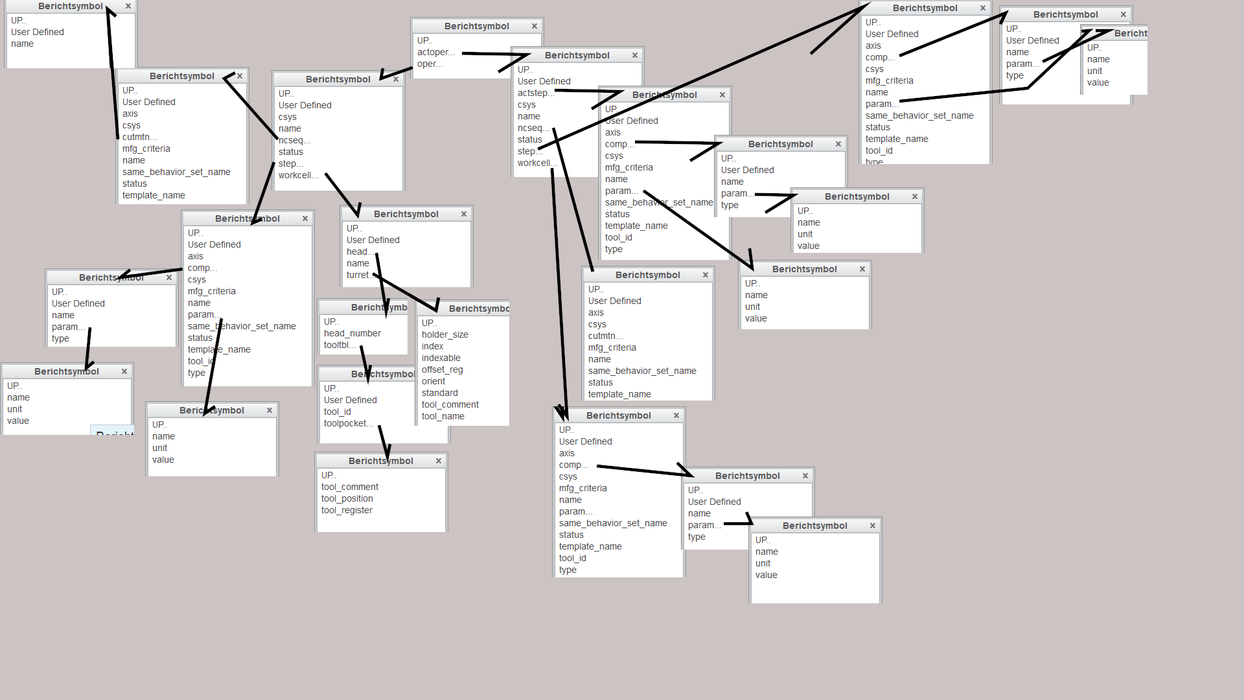
Pro/ReportI do not know how to access all the parameters you can access in drawing mode while in your manufacturing assembly – mfg.actoper.step for instance
There is no mfg.actoper.step, it is just another submenu to it. And then there is no step# but only name.
No number.
Here is a screenshot to show you all possible parameters:
- Mark as New
- Bookmark
- Subscribe
- Mute
- Subscribe to RSS Feed
- Permalink
- Notify Moderator
How can I set local parameters for every sequence with one command?
I believe you can do this via the process manager> tools> global parameters – you can set the parameter type and a default value… you might also consider global relations from this same menu if you want to include a relations to calculate the value of the parameter.
The example below will create parameter = GLOBAL_PRAM_TEST in NC sequences
- Mark as New
- Bookmark
- Subscribe
- Mute
- Subscribe to RSS Feed
- Permalink
- Notify Moderator
This is a good consideration, an it works!
I tried it before, but not in this way:
you can use a local variable in a global equation.
So you write in the Global Equation:
ZvarToUse=zmin
Unfortunately I can not use this Parameter to access it in the Processmanager!
But it shows:
I could use this new knowledge if I knew how to get a stepNumber# for every step..
then I could say globally:
myvariable="myfilename"+itos(stepNumber#)
- Mark as New
- Bookmark
- Subscribe
- Mute
- Subscribe to RSS Feed
- Permalink
- Notify Moderator
I am running Creo 8.0.7.0 and all my tests have been using a 5 axis mill workcell.
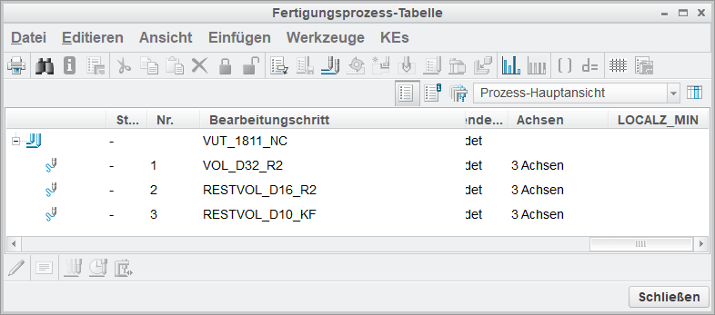
I added LOCALZ_MIN as shown and it appeared to work for me:
is this close to what you are trying to do but instead of PTC_MFG_PRM_CL_FILE = rel_model_name+"_"+ITOS(MACHINING_DISTANCE) you want PTC_MFG_PRM_CL_FILE = rel_model_name+"_"+ITOS(STEP_NUM) ?
Is it good or bad that if you re-order NC sequences it will change the name?
- Mark as New
- Bookmark
- Subscribe
- Mute
- Subscribe to RSS Feed
- Permalink
- Notify Moderator
I just posted an "idea" regarding this topic - please check it out, comment, vote
- Mark as New
- Bookmark
- Subscribe
- Mute
- Subscribe to RSS Feed
- Permalink
- Notify Moderator
To be honest, you guys lost me quite a while ago lol. I have read over everything you have posted, and tried to digest it and contribute, but I am not sure how you guys are even going about all of this.
I've never even used the process manager before this thread, let alone know what it is useful for...
- Mark as New
- Bookmark
- Subscribe
- Mute
- Subscribe to RSS Feed
- Permalink
- Notify Moderator
I did not intend to hijack your thread - my apologies
Back to your original question, here is a quick video (with audio) explaining how you might use relations in manufacturing to control workcell parameters and retract planes:
.
- Mark as New
- Bookmark
- Subscribe
- Mute
- Subscribe to RSS Feed
- Permalink
- Notify Moderator
Yes that will work, but I was hoping to basically do what you are doing by using relations, but based on the selected work center. All I am missing is the parameter for the work center, If I had that then my relations should work... Having to select a diff machine in the parameters isn't as user friendly as selecting the workcenter in the operation.
- Mark as New
- Bookmark
- Subscribe
- Mute
- Subscribe to RSS Feed
- Permalink
- Notify Moderator
Thank you, great work!
Well, I use Creo 3 M190
I can also use Creo 4, but there is nothing better 😕
I can add a global Relation that works like this one:
myvar = rel_model_name+"_"+ITOS(zmin)
and then I can see the correct value.
What I can not do is: use Step_num (There is no such parameter).
And what I fail to do is: create a new row with lets say localz_min in the process manager that shows a value.
Where do you create your own parameter?
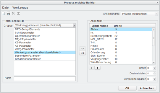
Do you create it also here, in "Toolsparameter" (user defined)?
Is it good or bad that if you re-order NC sequences it will change the name?
It is good, I need it to work that way. But as I said, there is not Parameter Step_num
- Mark as New
- Bookmark
- Subscribe
- Mute
- Subscribe to RSS Feed
- Permalink
- Notify Moderator
I add the parameter I created as a "feature parameter" and just type it in, then "add column" - very similar to configuring the model tree:
- Mark as New
- Bookmark
- Subscribe
- Mute
- Subscribe to RSS Feed
- Permalink
- Notify Moderator
Thank you!! It worked!
It is the feature parameter NOT the tools Parameters (User Defined).
I changed creo to english to find the correct Group
go into the C:\PTC\Creo x.0\Mxxx\Parametric\bin, copya the parametric.psf to a new one,
add this line to the bottom
// Add User specific environment or run applications below here
this line -> ENV=PRO_LANG=english
and then it is easier to find the right names and params.
Right now I can just guess, but in german it might be the KE-Parameter
And if I add zmin there, it also works! This way, I can generate a report with the zmin without calculating anything. The yknow then how deep the tool dives into the part if they want to go deep into a pocket.
The only thing that I need now is the step number 🙂
Thank you very much!
P.S.:
As has to be said again, we an look nto the saved xml files like the
mfg_session_setup.xml
for instance and findout how the parameters are named.
here is a little excerpt from it:
 <ColumnCollection LockedNum="2">
<Column Num="1" Width="4">
<Property Label="Schritt #" Name="STEP_NUM" Type="ANCPP_PARAM"/>
</Column>
<Column Num="2" Width="20">
<Property Label="Name" Name="PRO_E_FEAT_NAME" Type="NC_SETUP_ITEM"/>
</Column>
<Column Num="3" Width="20">
<Property Label="Werkzeug" Name="PRO_E_TOOL" Type="NC_SETUP_ITEM"/>
</Column>
<Column Num="4" Width="12">
<Property Label="SCHRUPP_AUFMASS" Name="ROUGH_STOCK_ALLOW" Type="MFG_PARAM"/>
</Column>
<Column Num="5" Width="8">
<Property Label="SCHLICHT_AUFMASS" Name="FINISH_STOCK_ALLOW" Type="MFG_PARAM"/>
As you can see, there is step_num, but it is not working. The rest of the parameters can be accessed.
To try out those that are of interest, you go into the equation editor and check them here:
P.S.: It has to do someting with the place where this parameter is accessed to.
You can see there is written also the TYPE.
I.e. Name="STEP_NUM" Type="ANCPP_PARAM"
So, what is the place where I can access an ANCPP_PARAM.
As you found out, the zmin is at:
Name="ZMIN" Type="MFG_INFO_PARAM"/>
So, the feature parameter is called the MFG_INFO_PARAM
- Mark as New
- Bookmark
- Subscribe
- Mute
- Subscribe to RSS Feed
- Permalink
- Notify Moderator
When I check the box "Always use Operation Retract" it is not even forcing any single step to retract to that operation Value.
So not even this is working for me (Still working with Creo 3 and being happy with this, for in newer versions are only new gimmicks but not really fixes implemented).
And I do not know the value either (it could be named "PRO_E_RETR_SURF_VALUE" but is not working..) and have to manually change the retract value for every step.
A workaround would be, that we export the steps that shall have a different retract value with the process manager

change the "PRO_E_RETR_SURF_VALUE" in an xml editor like notepad++,
and load this again with the process manager into the new project with the different machine.
here int the process manager
here, in the maching tab:
P.S.: i guess I am understanding the "Always use Operation Retract" wrong.
Sorry, maybe it helps in one or an other way
- Mark as New
- Bookmark
- Subscribe
- Mute
- Subscribe to RSS Feed
- Permalink
- Notify Moderator
ok, different approach:
Use the normal parameters.
create clearance as a parameter.
Write this into the field:
If this works also for you, then you can do something like, because you said you have not all values in your head, do something like this:
If You have machine1 clearance=40
machine2 clearance=50,
then you write inside the field clearanceMach1
and if it is the second machine clearanceMach2 and so on.
The Values are set in the parameter field
clearanceMach1=40
clearanceMach2=50
- Mark as New
- Bookmark
- Subscribe
- Mute
- Subscribe to RSS Feed
- Permalink
- Notify Moderator
Yes, this does work, but what I was wanting to know is the name of the parameter for the work center, so I could write a relation that selects the clearance for me. Something like this. The "mfg_oper_workcell_name" works as a parameter for the work center in drawings but doesn't seem to work in the machining model.
IF mfg_oper_workcell_name == "Haas"
clearance= 40.00
ELSE
ENDIF


