Community Tip - Did you get an answer that solved your problem? Please mark it as an Accepted Solution so others with the same problem can find the answer easily. X
- Community
- Creo+ and Creo Parametric
- Manufacturing (CAM)
- Facet feature - milling/manufacturing imported STL...
- Subscribe to RSS Feed
- Mark Topic as New
- Mark Topic as Read
- Float this Topic for Current User
- Bookmark
- Subscribe
- Mute
- Printer Friendly Page
Facet feature - milling/manufacturing imported STL - crazy problems
- Mark as New
- Bookmark
- Subscribe
- Mute
- Subscribe to RSS Feed
- Permalink
- Notify Moderator
Facet feature - milling/manufacturing imported STL - crazy problems
Hey guys! First time poster here!
The main reason for me to post here is because crazy things are happening.
What I've got:
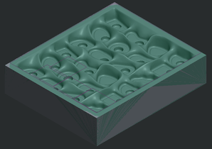
- clean, completely manifold (solid) STL file (checked with multiple programs)
- imported as facet feature in the reference model
- manufacturing model with mill windows defined
- milling using roughing, reroughing and finishing
What happens:
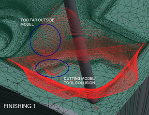
Somehow, Creo decides to mill something we can't see ... the tool collides with invisible surfaces or goes through the reference part.
Discoveries:
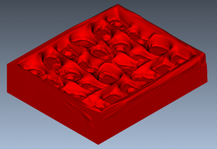
when the model is opened in Vericut simulation, we can see our reference part is distorted. Though in Creo everything seems okay.
This distortion seems to be the crazy invisible things which are happening.
How does this happen? Is there any way to fix this?
- Mark as New
- Bookmark
- Subscribe
- Mute
- Subscribe to RSS Feed
- Permalink
- Notify Moderator
I have never tried to machine a STL file before. I know you said the file was a solid but? Not sure if that is the problem but I would start by Trying to import the file as a solid model rather than a faceted model or get a Step file or whatever the solid was made from. If that isn't possible I would then try using just a good ole volume roughing routine. Sometimes the new roughing goes a little crazy with odd shaped parts in my experience especially the retract. I always set the retract to always and that seems to help some of the issues
- Mark as New
- Bookmark
- Subscribe
- Mute
- Subscribe to RSS Feed
- Permalink
- Notify Moderator
Thank you for your answer! Though I don't think this is a solution ...
It's not possible to import the file as a solid model because the origin is a scan. It can be called a solid STL because there are no holes in the mesh, however in Creo this will not be solid geometry. Volume roughing is never possible on a facet feature.
The file is too heavy to convert to STEP and still be smooth enough.
There is also the possibility to create a shrinkwrap, this way volume roughing is possible. When the full model is converted the surface is way too blocky. So I cut it up in parts, but then Creo can't handle the files anymore (too much/loading times too long)
I'm guessing Creo is wrongly interpreting the vertices in the background. Maybe there is an option to recalculate the mesh somewhere? (maybe a different program ... restyle/reverse engineering is not available for us in Creo)
- Mark as New
- Bookmark
- Subscribe
- Mute
- Subscribe to RSS Feed
- Permalink
- Notify Moderator
Could some of the vectors on the facet be pointing in the wrong direction (inward instead of outward) and therefor causing retract to be inside the part?


