Community Tip - New to the community? Learn how to post a question and get help from PTC and industry experts! X
- Community
- Creo+ and Creo Parametric
- Manufacturing (CAM)
- Re: Threadmill expertise needed, NPT
- Subscribe to RSS Feed
- Mark Topic as New
- Mark Topic as Read
- Float this Topic for Current User
- Bookmark
- Subscribe
- Mute
- Printer Friendly Page
Threadmill expertise needed, NPT
- Mark as New
- Bookmark
- Subscribe
- Mute
- Subscribe to RSS Feed
- Permalink
- Notify Moderator
Threadmill expertise needed, NPT
I am trying to implement thread mills into Creo negating the need to use a code generator from the manufacturer, so that code can be reliably posted from the manufacturing model.
- I am having troubles setting the depth of the NPT, as there seems to be no "thread length" in the parameters, or depth option. I am not completely sure, but this depth appears to be controlled by entering the number of teeth on the cutter, in the "flute" field of the tool information. This seems like a very odd way of controlling depth, is it how it is done?
- The code generated when doing an NPT thread mill is many lines of point movement rather than a few lines of canned cycle. There is no G03 movements output at all, and this makes for a very awkward and VERY long program, any workarounds?
- Placement of the thread when choosing start and end. I am having problems with the placement of the thread, I have attached screenshot to help explain.
In this demonstration, I have made a sample part that is .500 in. thick. I will try to thread a 1/8-27 NPT into it.
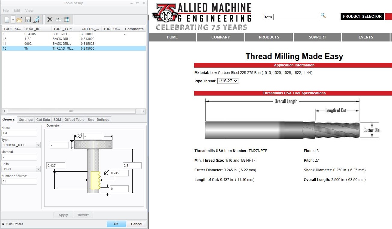
Here you can see my how my tool is defined, it is an Allied TM27NPTF in case anyone wants to spec it out further.
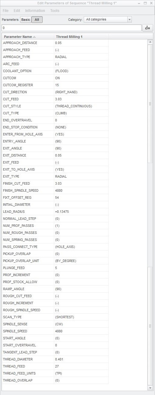
Here are my parameters
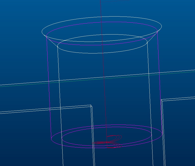
I want a normal NPT from the top of the part down, but here is the resulting tool paths that I get. This is with start and end both set to "auto"
Here I selected the top of the part for start, and left the end as "auto", it gives me the same results as when both on auto. Note that if I try to select the bottom of the part here as the start, and leave the end on "auto", it removes the tool path
Here the start is still set to the top of the part, but now the end is set to the bottom of the part, yet the tool path is at the bottom and does not complete the thread to the top of the part.
This is the same as above, only reversed. So the start is now set to the bottom of the part, and the end is set to the top of the part. Now the tool path is to far above the part.
Lastly, we have the start set to auto, and the end set to the bottom of the part. Note that if I try to select the top of the part here as the end, and leave the start on "auto", it removes the tool path.
So aside of putting both start and end to the top of the part, or the bottom of the part simultaneously, I have now exhausted all possible combinations without achieving a normal NPT tool path. I should also mention that I also tried calculating the NPT depth and creating a plane at that depth, setting the "end" to the plane I made, but it still did not make the desired tool path.
- Labels:
-
General
- Mark as New
- Bookmark
- Subscribe
- Mute
- Subscribe to RSS Feed
- Permalink
- Notify Moderator
Question 1: Yes the number of teeth sets the depth it seems. I was confused by this at first also, but it seems to work.
Question 2: make sure your parameter Circ_interpolation is set to arc_only. this make far less lines of code than points_only.
Question 3: the thread milling has always started at the bottom and cut up. I don't believe you can reverse this unless you do It with a trajectory which is the way I used to cut the NPT threads udf that made a tapered helical curve with a single point threading tool and a trajectory curve.
The way we do NPT threads now is with a cosmetic thread that just sets the diameters and depths and calls it a NPT hole of what ever size needed for 1/8 1/4 and 3/8 which is what we do the most often. We don't use the hole function for the tapered NPT. Our engineering doesn't like it I guess because you basically have to create 2 holes. The straight drilled hole and the tapered thread.
here is a 1/8 27 threadmill multi pass path picture
- Mark as New
- Bookmark
- Subscribe
- Mute
- Subscribe to RSS Feed
- Permalink
- Notify Moderator
Thanks for the quick response. As for the "Circ_interpolation" parameter, I do not seem to have that parameter available, even when looking for it hidden under tools/visibility. Any ideas?
Also for the NPT thread, I do understand that it starts at the bottom and threads itself up to the top, that is ok. I will try to clarify, I was saying that I was unable to get the thread to end at the top of the part. The thread seems to want to start from the very bottom surface of my part, and thread towards the top only a small distance, instead of starting somewhere in the middle of the hole, and threading fully up past the top of the part, if that makes any sense.
- Mark as New
- Bookmark
- Subscribe
- Mute
- Subscribe to RSS Feed
- Permalink
- Notify Moderator
Neal,
not sure why you are not seeing the circ_interpolation parameter?
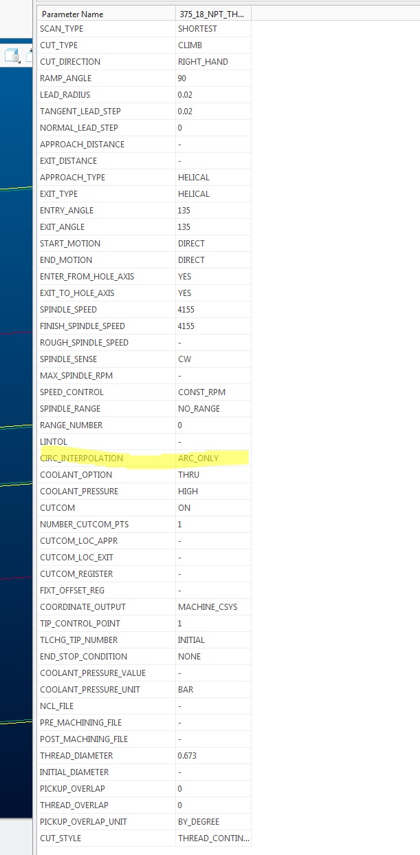
if you are trying to spin the thread mill all the way out of the hole then you need to look at the over travel parameters. the start_overtravel makes the cutter go deeper into the hole and the end_overtravel makes the come out of the hole.

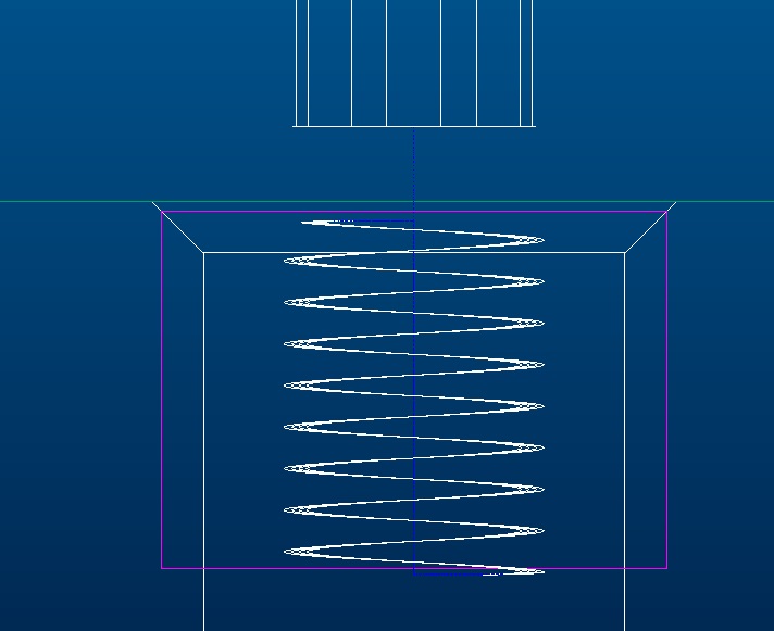
the last picture is a .600 deep thread with an end overtravel of.6 Hope this helps with what you are trying to do.
- Mark as New
- Bookmark
- Subscribe
- Mute
- Subscribe to RSS Feed
- Permalink
- Notify Moderator
That is exactly what I am trying to do. So essentially you have to fill out the overtravel exit, or in your example you would get no travel since it is .600 deep, and overtravel is also set to .600, take away the overtravel and it would be 0.
So what I am doing now on my end, is creating a plane to control the depth, and setting the "end" to that plane, and then the "start" to the top surface. But when I try, I am unable to get the tool path to helix out to the correct height if I match it to the depth in overtravel (my example is 0.2348 deep, and 0.2348 exit overtravel), I believe that this is for some reason related to the tool "flutes" setting again, even though I have them set to the physical number of teeth on the tool. But as long as I overtravel far enough, I will be able to clear the hole. I just hope that the "flute" setting does not affect the actual helix or TPI, since it does seem to be wrong.
I really wish I could set the "circ_interpolation", I am using Creo 3, and cannot find it anywhere, not even in tools/visibility.
It should be around the highlighted areas (and I have searched for it when reordered to alphabetic)
- Mark as New
- Bookmark
- Subscribe
- Mute
- Subscribe to RSS Feed
- Permalink
- Notify Moderator
Neal,
If you are using a multi flute thread mill you should only need to make 1 revolution to create the thread. If you are using a single flute thread mill then you need to do the over travel. I usually drop to the bottom of the hole using the hole axis with a lead in and lead out to enable cutter compensation. Then make 4 rough passes with like .005 to .010 increments and 1 drift for NPT threads in steel.
Not sure why you don't have the circ_interpolation parameter? I have had it since Creo 2.0 if not before I believe. It switches from point to point to arcs where possible. one thing I just noticed is you're pictures are of the site file parameters the circ_interpolation is in the manufacturing parameters
I am in no way an expert on thread milling but I know what works for me. Maybe someone else can add a little input.
- Mark as New
- Bookmark
- Subscribe
- Mute
- Subscribe to RSS Feed
- Permalink
- Notify Moderator
Yes I am using a multi flute thread mill. In order to make it make only 1 revolution, would I put "1" in the "flute" field of the tool?
- Mark as New
- Bookmark
- Subscribe
- Mute
- Subscribe to RSS Feed
- Permalink
- Notify Moderator
No the tool needs to be multi flutes
- Mark as New
- Bookmark
- Subscribe
- Mute
- Subscribe to RSS Feed
- Permalink
- Notify Moderator
Neal and Steve,
I'm sure it is possible to let the thread mill start at the upper surface to go down helically to the bottom surface.
I did it last week, but I'm not sure about the setting of the parameters. For that I have to look in my notes about thread milling. Next tuesday, I can tell you about the right parameters because then I'm in my office again where I have my notes and a PC with Creo.
You can also cut the thread in different steps by setting the parameter "number of profile passes" to 3 for example and setting the parameter "profile increment" to 0.5mm for example.
I don't use CUTTER COMPENSATION to ON but I let it to OFF.
You don't have to calculate anything based on the number of teeth on the milling cutter.
I always use a single point cutter, but there is no diffecence with mort teeth on the cutter.
As a conclusio I will tell you that it works very well in Creo when you give the right input to the system.
Plaese send me an e-mail to jef.verheyen@kuleuven.be
Best regards,
Jef


