Community Tip - Want the oppurtunity to discuss enhancements to PTC products? Join a working group! X
- Subscribe to RSS Feed
- Mark Topic as New
- Mark Topic as Read
- Float this Topic for Current User
- Bookmark
- Subscribe
- Mute
- Printer Friendly Page
Catenary with load
- Mark as New
- Bookmark
- Subscribe
- Mute
- Subscribe to RSS Feed
- Permalink
- Notify Moderator
Catenary with load
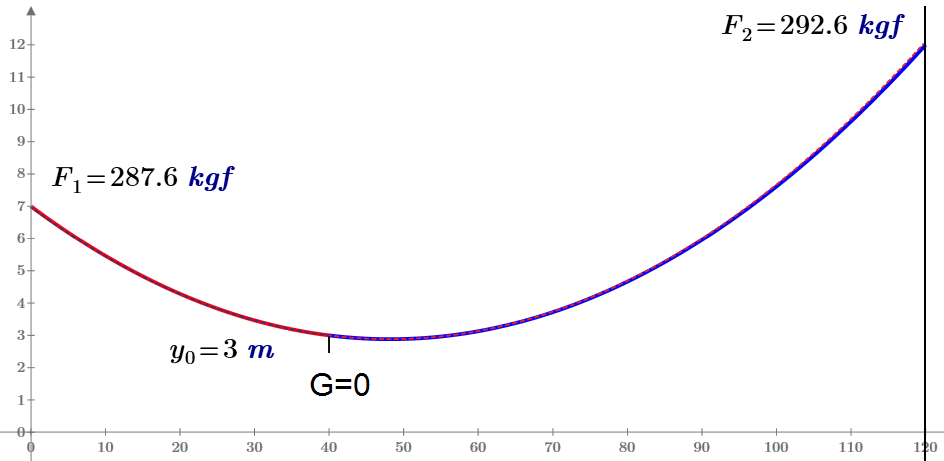
I hope I have solved this old interesting problem - One catenary problem
See please pictures and attach (15 and Prime).
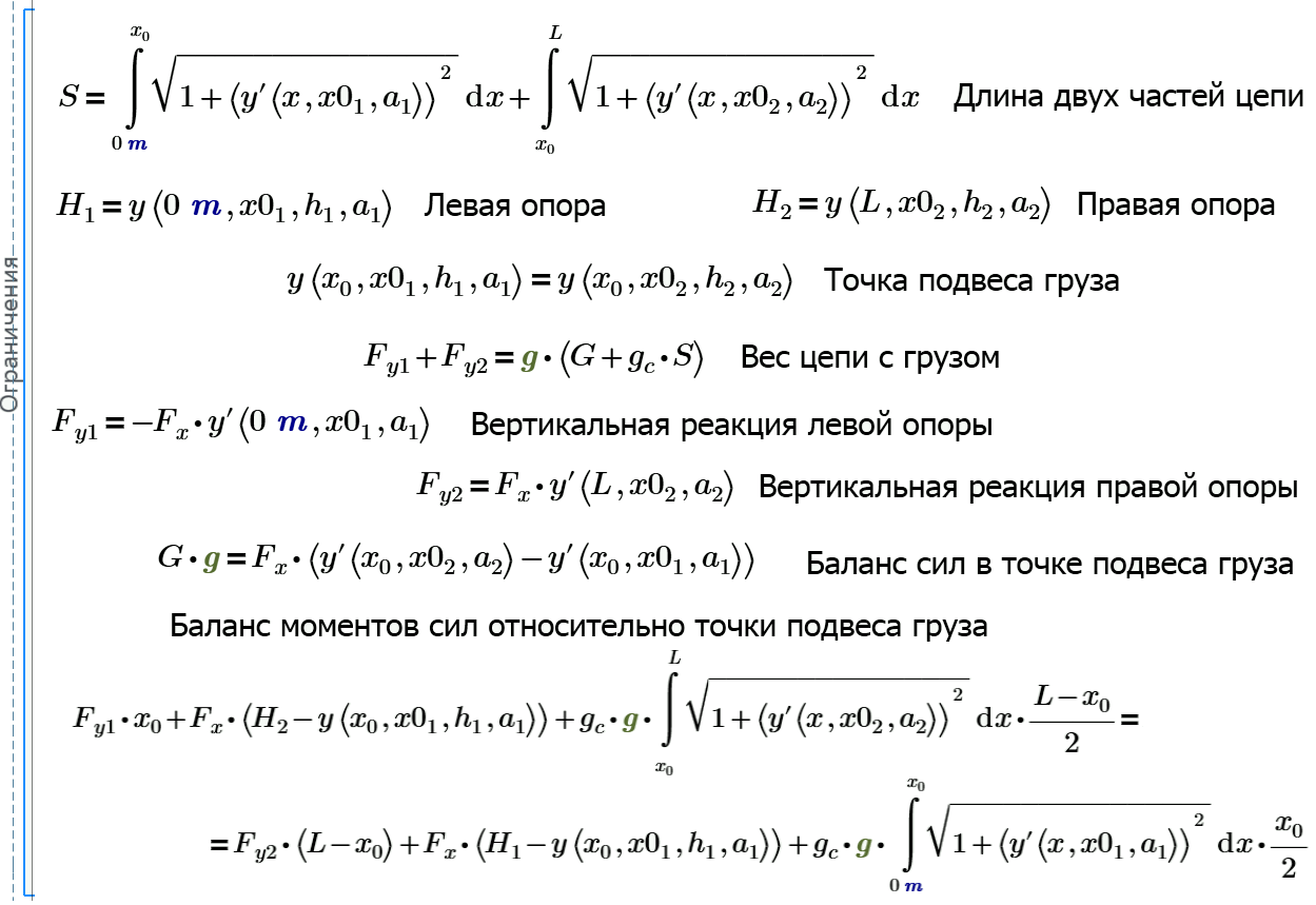
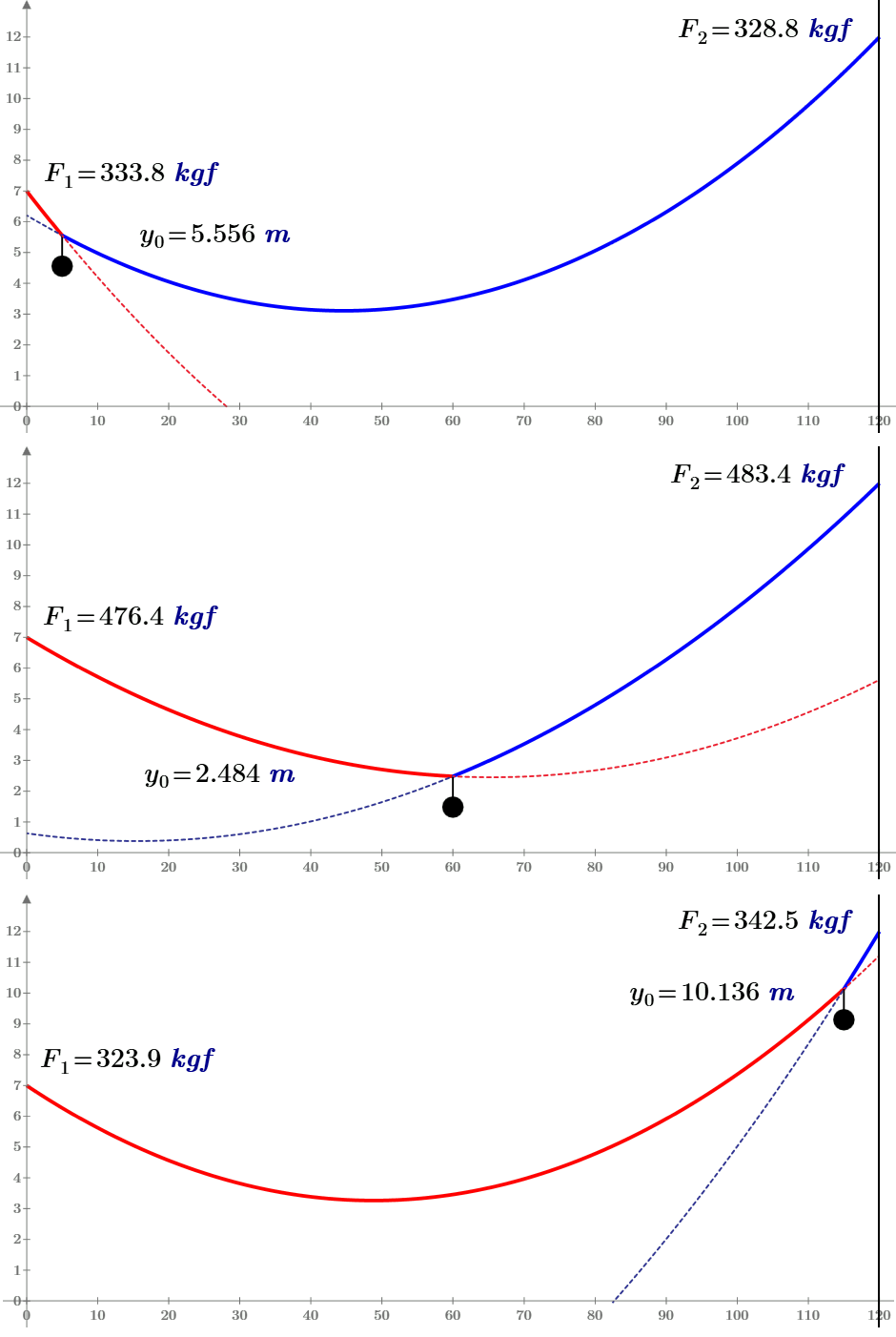
But at G=0 and x.0=1 m I have not one chain - is it an error of Math model or of a numerical method of 9 equations solution?
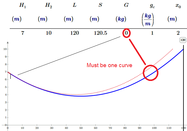
At x.0=40 m and others not at two fix points all is OK
Werner! Where are you?
Solved! Go to Solution.
- Labels:
-
Other
Accepted Solutions
- Mark as New
- Bookmark
- Subscribe
- Mute
- Subscribe to RSS Feed
- Permalink
- Notify Moderator
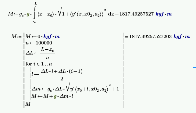
Well, I was going to say that your expression for Delta_m was wrong, because it should be gc*Delta_S, not gc*Delta_L, but I see you already fixed that ![]()
So your fixed program points to the correct form for the integral:
- Mark as New
- Bookmark
- Subscribe
- Mute
- Subscribe to RSS Feed
- Permalink
- Notify Moderator
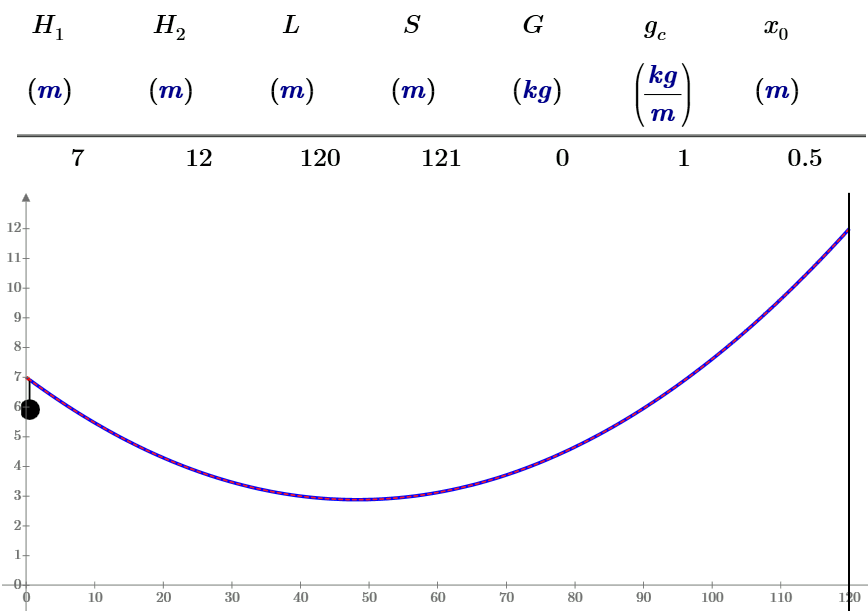
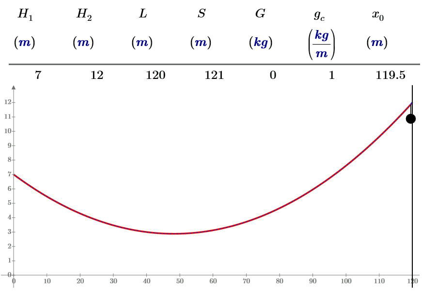
I can not insert a video. See please two frame of two cases
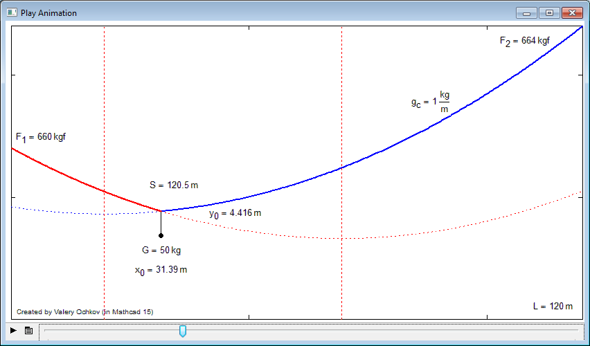
and with error
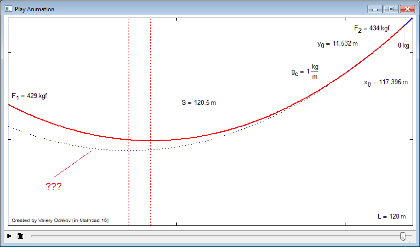
and video (may by it is OK)
- Mark as New
- Bookmark
- Subscribe
- Mute
- Subscribe to RSS Feed
- Permalink
- Notify Moderator
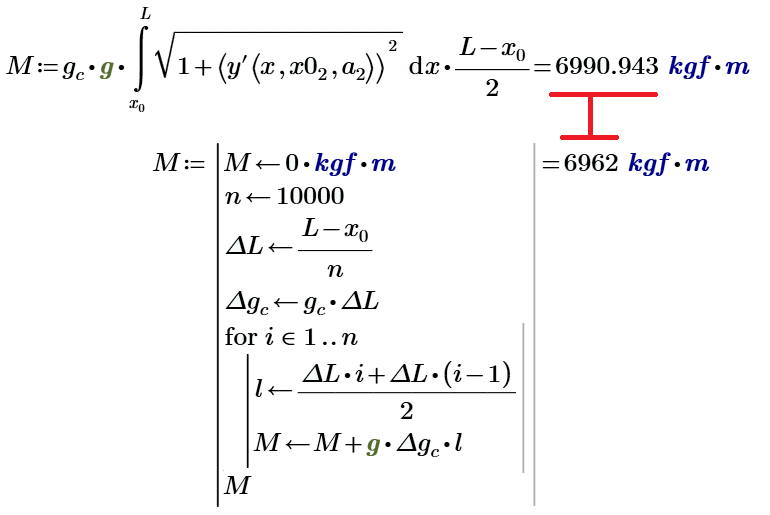
May by the error is here
- Mark as New
- Bookmark
- Subscribe
- Mute
- Subscribe to RSS Feed
- Permalink
- Notify Moderator
I'm not a big fan of typing ![]()
Could you post a worksheet with the evaluated integral and the program.
- Mark as New
- Bookmark
- Subscribe
- Mute
- Subscribe to RSS Feed
- Permalink
- Notify Moderator
Richard Jackson wrote:
I'm not a big fan of typing
Could you post a worksheet with the evaluated integral and the program.
See please the end operator in attach (Prime 3)
- Mark as New
- Bookmark
- Subscribe
- Mute
- Subscribe to RSS Feed
- Permalink
- Notify Moderator
I think it's just a numerical issue. With x.0=40m you can still see a difference between the two curves at 120m, it's just not as obvious. When x.0=1m you are extrapolating the curve by more than a factor of 100, so even the smallest error in the calculated curve becomes very obvious.
Edit: now I'm not so sure. If I change the algorithm for Find, or if I change TOL and CTOL, it makes no noticeable difference. If it were a numerical limitation I would expect something to change.
- Mark as New
- Bookmark
- Subscribe
- Mute
- Subscribe to RSS Feed
- Permalink
- Notify Moderator
Thanks, Richard.
I think, the error is in the torque formula.
- Mark as New
- Bookmark
- Subscribe
- Mute
- Subscribe to RSS Feed
- Permalink
- Notify Moderator
I hope I have correct solution.
Now we can solve new task with 2, 4, 4 loads ![]()
The 9-th equation must be
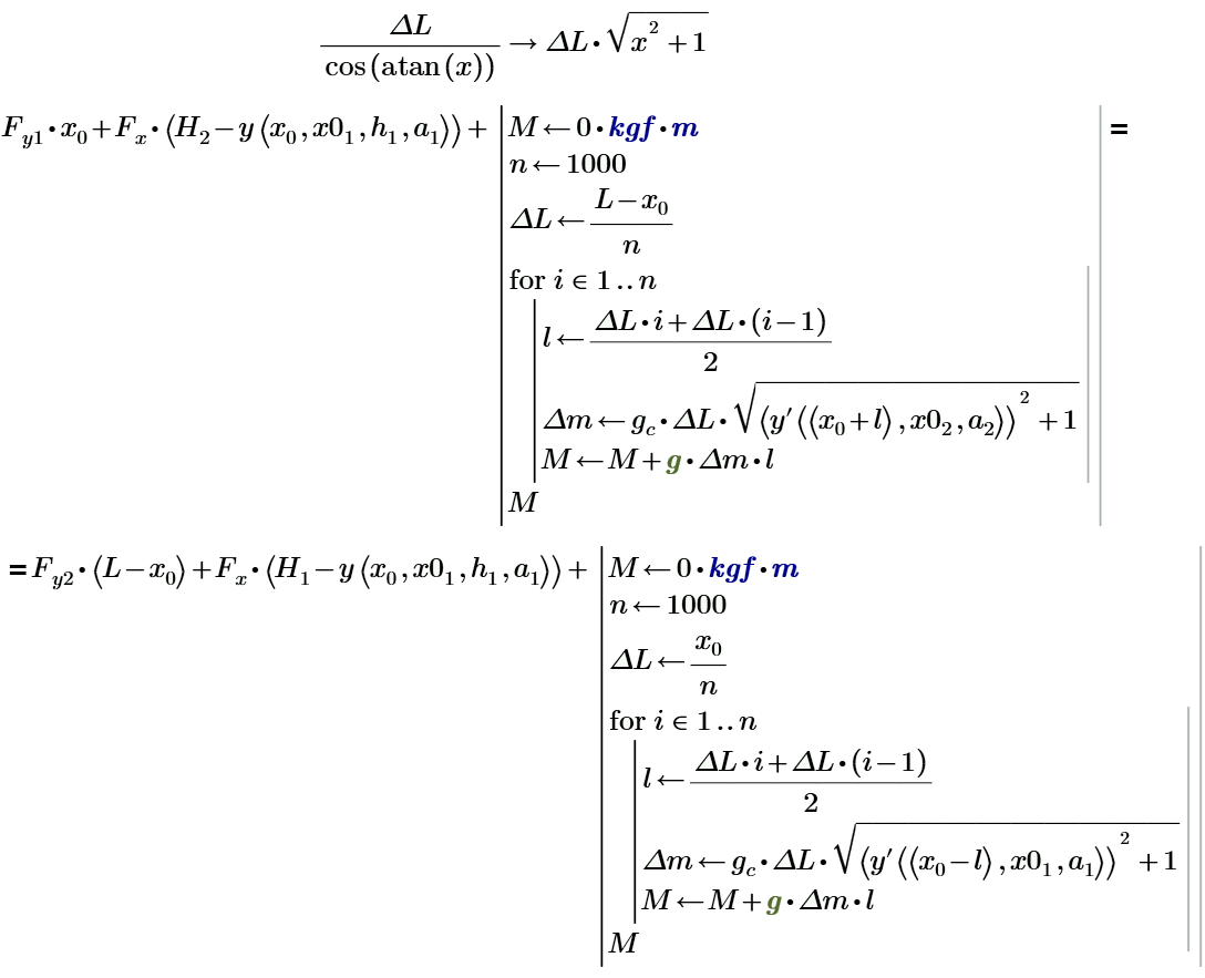
and no problems
- Mark as New
- Bookmark
- Subscribe
- Mute
- Subscribe to RSS Feed
- Permalink
- Notify Moderator
Well, I was going to say that your expression for Delta_m was wrong, because it should be gc*Delta_S, not gc*Delta_L, but I see you already fixed that ![]()
So your fixed program points to the correct form for the integral:

- Mark as New
- Bookmark
- Subscribe
- Mute
- Subscribe to RSS Feed
- Permalink
- Notify Moderator
Thanks Richard. Would you like to be one coauthor of this chapter/article? Welcome!
I have added your integral in the book with one remark:
На рисунке 7.15 показано уточненное уравнение баланса моментов сил, в которое было вставлено определение момента сил от веса провисающих цепей, заданное с помощью цикла с параметром. Цепь разбивается на 1000 элементарных кусочков (элементов) со своим моментом сил, которые суммируются.
Но сумма (рис. 7.15) предпочтительней интеграла в русле основной идеи первого этюда книги, утверждающей, что в формуле должна быть видима ее физико-математическая суть. В сумме она сразу видна (суммирование моментов сил от элементарных участков цепи), а в интеграле – нет.
And more
Наши расчеты показывают, что мост или канатную дорогу нужно испытывать не только при максимальной, но и при минимальной (нулевой) нагрузке. И даже при отрицательной – см. рис. 7.19.
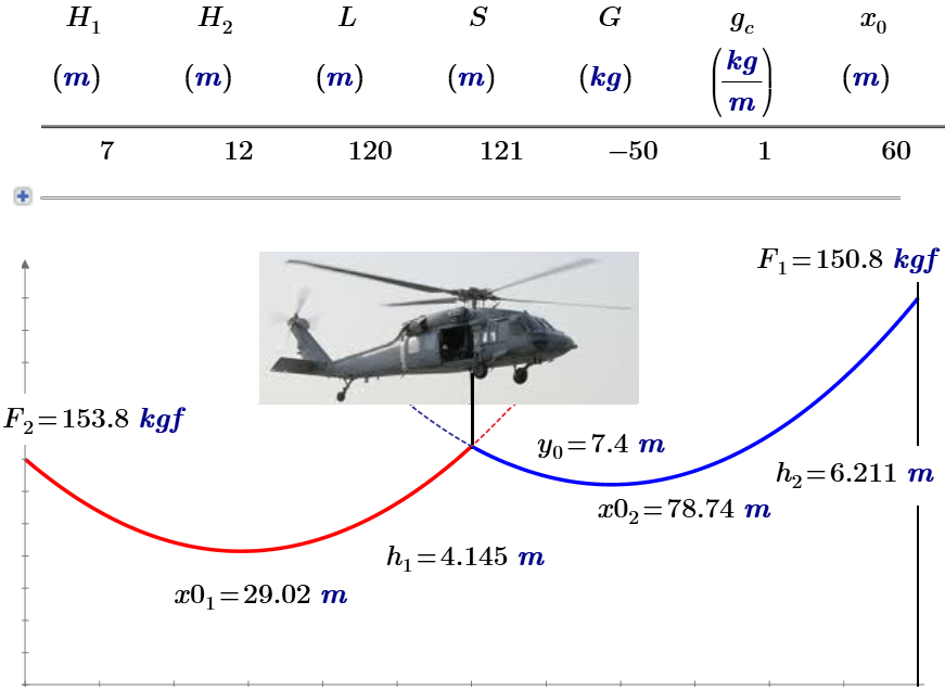
Мы уже упоминали в сноске, что инженер должен решать не просто технические, а технико-экономические задачи. Если, например, под нашей ЛЭП должен проплыть всего лишь раз аномально высокий объект, то можно не строить высокие мачты или не натягивать излишне провода, а… приподнять их с помощью, например, вертолета. Кстати можно заметить, что у летящего с внешней подвеской вертолета трос тоже прогибается не по прямой, а по цепной линии. И это тоже можно обсчитать, используя подходы, описанные в этом этюде.
- Mark as New
- Bookmark
- Subscribe
- Mute
- Subscribe to RSS Feed
- Permalink
- Notify Moderator
Thanks Richard. Would you like to be one coauthor of this chapter/article? Welcome!
If you were to ask that question a year from now you would probably get a different answer, but at the moment I really don't have time to coauthor even one chapter. Sorry, but thanks for asking ![]()
As evidence of that, I'll remind you that I still owe you a translation ![]()
- Mark as New
- Bookmark
- Subscribe
- Mute
- Subscribe to RSS Feed
- Permalink
- Notify Moderator
Thanks for this! I have a zipline that needs tensioning, and your MathCad sheet lets me identify a suitable cable length and tension.
However, my setup is slightly more complicated as the lower support point is actually a post and the cable continues over the top of the post and is anchored to the ground 10m further away, as illustrated. The cable can slide over the top of the post. I am thinking about extending your equations to include this section of the cable, which is of course another catenary. Do you see any reason why this shouldn't be possible?
Thanks!
Ian Viney
- Mark as New
- Bookmark
- Subscribe
- Mute
- Subscribe to RSS Feed
- Permalink
- Notify Moderator
Let do it and I will try help you!
- Mark as New
- Bookmark
- Subscribe
- Mute
- Subscribe to RSS Feed
- Permalink
- Notify Moderator
Thanks for your encouragement! 😀 I am a complete novice with MathCad (this is my first sheet), and I haven't done calculus for 40 years, so please be patient...
I have made some modifications in the attached file to have a third "anchor" catenary:
It seems to work (though I haven't tested it much), but I am not fully convinced it's 100% correct. In particular:
- a1, a2 and a3 all come out with the same value. This seems suspicious to me!
- The strain in the cable where the anchor catenary meets catenary #1 (i.e. where black meets red) is different in the two catenaries. Intuitively it feels like they should be the same! I will add another constraint tomorrow and see what happens.
How sensitive is MathCad to the guess values?
A very novice question: some constraints are greyed out, presumably inactive. How do you do that?
Also, in the last constraint equation I'd be interested to know why you calculate the integrals iteratively rather than letting MathCad do it? Why does it give a different result?
Kind regards,
Ian.
- Mark as New
- Bookmark
- Subscribe
- Mute
- Subscribe to RSS Feed
- Permalink
- Notify Moderator
Hello again,
I added this constraint to my sheet but it would not produce an answer:
I looked further into the a1, a2 and a3 parameters being equal. I went back to your sheet and it also generates a1 and a2 being equal. In fact, I changed all occurrences of a2 to a1 and it still produced the same results! I wasn't expecting this, but perhaps every catenary is equal in the sense that if you go far enough along it you can find a section that will fit your desired points?
I also tried to understand the final constraint for balancing the moments of forces at the point of suspension of the load:
This is greyed out (presumably disabled) in favour of the iterative solution, which calculates the same thing:
The integral gives the length of the cable on either side of the load, and each is multiplied by the x distance that is halfway to the support. However, shouldn't we use the distance to the centre of mass of that part of the cable? Since the catenary segments have end points at different heights, the halfway point along the x axis will not be the point at which we have half the segment length (and therefore half the weight). In other words,
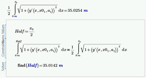
I'm not sure of the best way to find the x value that corresponds to half the length, but I did it with a solve block to demonstrate the difference:
x0 was 70m, so x0/2 was 35m.
Any comments would be welcome!
Kind regards,
Ian.
- Mark as New
- Bookmark
- Subscribe
- Mute
- Subscribe to RSS Feed
- Permalink
- Notify Moderator
OK, I now see that the iterative calculation is calculating the moment of each small increment, so it is giving the correct result. I initially thought it was doing the same integral as in the equation preceding it, but it's different.
Ian.
- Mark as New
- Bookmark
- Subscribe
- Mute
- Subscribe to RSS Feed
- Permalink
- Notify Moderator
I've tested it out some more and it seems to give reasonable answers. However, if the supplied cable length is much longer than the minimum straight-line distance between the points, it doesn't converge on an answer. I use an S value about 8cm longer than the straight lines.
If we increase the load, the anchor catenary becomes more taut, as expected:
The attached sheet doesn't do anything significantly different from the previous one; it just presents more data.
I'm still unsure about the forces at the left support (0,H1) being different for the black and red catenaries. And I don't yet have an intuitive understanding of why all three catenaries end up with the same parameters (a1=a2=a3). Any thoughts?
Regards,
Ian.
- Mark as New
- Bookmark
- Subscribe
- Mute
- Subscribe to RSS Feed
- Permalink
- Notify Moderator
I am very glad that my old work helped you. I really want to "move" into your work, but, unfortunately, I'm currently busy with other work - I'm finishing writing a new book about Mathcad and Python.
Good luck!


