- Subscribe to RSS Feed
- Mark Topic as New
- Mark Topic as Read
- Float this Topic for Current User
- Bookmark
- Subscribe
- Mute
- Printer Friendly Page
Direction Field Plots (ODE's)
- Mark as New
- Bookmark
- Subscribe
- Mute
- Subscribe to RSS Feed
- Permalink
- Notify Moderator
Direction Field Plots (ODE's)
I've searched the forum, and all I can find are some old posts on the subject.
If I am given an Ordinary Differential Equation (ODE), and am told to plot the direction field, can I do so in Mathcad 14?
For example:
Graph a direction field. In the field, graph several solution curves, particularly those passing through the points (x,y)
y' = -2*x*y (0,.5), (0,1), (0,2)
Is this possible in Mathcad?
Solved! Go to Solution.
- Labels:
-
Calculus_Derivatives
Accepted Solutions
- Mark as New
- Bookmark
- Subscribe
- Mute
- Subscribe to RSS Feed
- Permalink
- Notify Moderator
Yes, I was just about to edit that post and attach the sheet but couldn't do so because you had already answered 😉
Here is the sheet. Please note that I have omitted the numbering of the x- and y-axis as this would not reflect the real x-/y-values as already described.
If you couldn't figure out how to do I may post a version using my 2D vector routine later.
EDIT: Changed the attached file; small error corrected
- Mark as New
- Bookmark
- Subscribe
- Mute
- Subscribe to RSS Feed
- Permalink
- Notify Moderator
Yes, you can do so called vector field plots in Mathcad 14 & 15 (not in Prime2). Look it up in the help.
But there are some limitations and drawbacks. These plots basically are 3D-plots and you would typically create a matrix of values and plot it. So the values at the ordinate and abscissa are not real x- and y-values but just the indices of your matrix elements.
- Mark as New
- Bookmark
- Subscribe
- Mute
- Subscribe to RSS Feed
- Permalink
- Notify Moderator
I looked at the help, and I honestly don't know where to start.
- Mark as New
- Bookmark
- Subscribe
- Mute
- Subscribe to RSS Feed
- Permalink
- Notify Moderator
Its not as straightforward as one may like it to be. Mainly because its a 3D plot. So plotting the solution curves is not that intuitive either, but its possible. Maybe I find more time later to eleborate more on this.
For now a short starter. You can plot a vector field basically in two ways:
1) Plot two matrices, one would hold the x-component, the other the y-component of the vectors
2) Plot a single matrix consisting of complex numbers, the real part being the x-component, the imaginary part the y-component of the vectors.
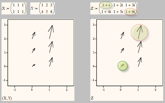
You have to notice a few things:
You have not much control about the position the vectors are plotted at. The position is defined by the matrix indices (and is affected by the value of ORIGIN). So assuming we stay with ORIGIN=1 you cannot have negative values here or non integers. So usually the scaling on the axis will not reflect the real x- and y-cvalues.
Also note that in the plot the row indices are horizontal and the column indices vertical from bottom upwards. So you may see it as the matrix turned for 90° counterclockwise.
The vectors are scaled so that the largest vector is of length 1.
So to create the necessary vector of slopes I usually find it easier to handle to use a matrix with complex numbers. The RHS of your ODE gives you a fine formula for the slope in each point so its not that difficult to obtain a matrix of slope values. You will then have to normalize those vectors later so all a drawn with equal length.
How do you intend to get the solution of the ODE? Using the numeric odesolve() or simply use the manual derived solution(s) C*e^(-x^2) ?
BTW, because of the drawbacks of Mathcads vertor field plot and also because this is a missing feature in Prime I developed some months ago a toolbox to be able to create vector field plots using a normal 2D-plot. You can find it here: http://communities.ptc.com/docs/DOC-3503 . I also had included as an example the slope field of an ODE along with some solution curves.
- Mark as New
- Bookmark
- Subscribe
- Mute
- Subscribe to RSS Feed
- Permalink
- Notify Moderator
I think this may put me in the right direction.
I took a look at your other post, and I was able to download and open the mathcad worksheet. It seems that your example for Slope field of a differential equation is exactly what I need - unfortunately I am having trouble following how it works. You have an ODE, but you also have an initial condition, which I do not have. However, this is exactly the type of plot I need, because I do need to plot lines going through a few points, which is exactly what you have.
- Mark as New
- Bookmark
- Subscribe
- Mute
- Subscribe to RSS Feed
- Permalink
- Notify Moderator
Also, how would I normalize the data so that all of the direction arrows are the same length?
- Mark as New
- Bookmark
- Subscribe
- Mute
- Subscribe to RSS Feed
- Permalink
- Notify Moderator
david h wrote:
Also, how would I normalize the data so that all of the direction arrows are the same length?
You divide each vector by its magnitude.
- Mark as New
- Bookmark
- Subscribe
- Mute
- Subscribe to RSS Feed
- Permalink
- Notify Moderator
You have an ODE, but you also have an initial condition
You have an initial condition if you are going for a specific solution, e.g. you demanded a curve going through (0/5). So y(0)=2 is your initial condition. If you are using Mathcads numerics to solve your ODE you can turn the solve block into a function to get "all" solutions. Like this: f(a):=Odesolve(x, xmax). But Mathcad would solve for 0 (because thats set in your initial condition) to xmax only, so you will have either the graph to the left or to the right of the y-axis. If you want both you have to solve twice and then combine the functions. Anyway, with f(2,x) you have the one solution function you can plot in 2D.
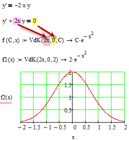
But plotting the slope field has nothing to do with solving the ODE. And in case of that simple ODEs its probably best if you provide the solution function yourself.
Unfortunately Mathcad provides no way to solve an ODE symbolically. I once wrote a sheet which does exactly that, but it was quite tricky and would work for simple first order ODEs only. Your example would be no problem, though 😉 So in case you are interested I attach that sheet.
- Mark as New
- Bookmark
- Subscribe
- Mute
- Subscribe to RSS Feed
- Permalink
- Notify Moderator
I am still digesting all of this...![]()
The thing is, this is a homework problem and I have a choice of drawing it by hand or using a computer program. I'd like to make sure I understand how to do it in MathCAD because I am sure I will have to do it again.
Right now I am trying to use your other worksheet to solve the problem that I posted. I am trying to go through line by line to see exactly how it works, so that I fully understand. I am supposed to fully understand direction field plots - and I need a way to re-create them in MathCAD for the future.
anyway, thanks again. Hopefully I will be able to edit your other workbook to solve my problem. Hopefully.
- Mark as New
- Bookmark
- Subscribe
- Mute
- Subscribe to RSS Feed
- Permalink
- Notify Moderator
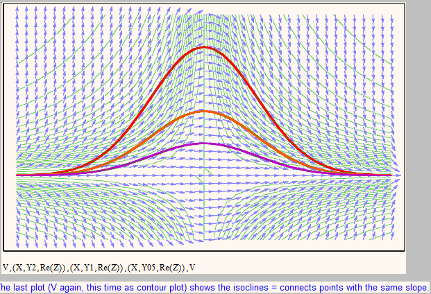
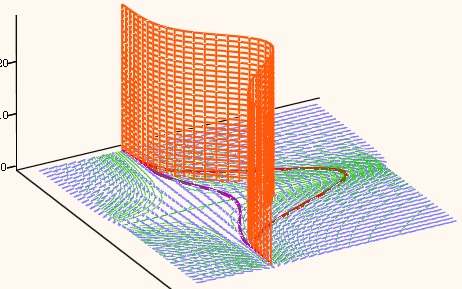
Here is the slope field plot of your function doing it with Mathcads own (3D) vector field plot.
The plotting of the specific solutions is quite tricky as in reality I would plot cylinders which look like the solution graphs when seen in z-direction and the plot a contourgplt of them (all contour lines would be one on top of the other of course). If you are interested what I really plot you can turn one of the three contourplots (e.g. Plot3) into a surface plot in the format menu. Now you can turn and zoom the graph in 3D.
- Mark as New
- Bookmark
- Subscribe
- Mute
- Subscribe to RSS Feed
- Permalink
- Notify Moderator
This is exactly what I need!
Could you post the source for this?
You have been extremely helpful!
- Mark as New
- Bookmark
- Subscribe
- Mute
- Subscribe to RSS Feed
- Permalink
- Notify Moderator
Yes, I was just about to edit that post and attach the sheet but couldn't do so because you had already answered 😉
Here is the sheet. Please note that I have omitted the numbering of the x- and y-axis as this would not reflect the real x-/y-values as already described.
If you couldn't figure out how to do I may post a version using my 2D vector routine later.
EDIT: Changed the attached file; small error corrected
- Mark as New
- Bookmark
- Subscribe
- Mute
- Subscribe to RSS Feed
- Permalink
- Notify Moderator
Thank you for all of your effort. I think I follow the spreadsheet now!
- Mark as New
- Bookmark
- Subscribe
- Mute
- Subscribe to RSS Feed
- Permalink
- Notify Moderator
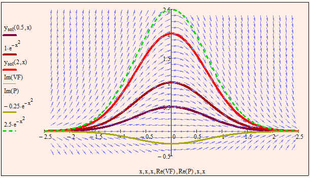
Here' s the second sheet using 2D plot.
The advantage is that axis scaling is correct and plotting of solutions is as usual and not that laborious.
