Community Tip - Learn all about the Community Ranking System, a fun gamification element of the PTC Community. X
- Subscribe to RSS Feed
- Mark Topic as New
- Mark Topic as Read
- Float this Topic for Current User
- Bookmark
- Subscribe
- Mute
- Printer Friendly Page
Electrical Engineering Challenge #3
- Mark as New
- Bookmark
- Subscribe
- Mute
- Subscribe to RSS Feed
- Permalink
- Notify Moderator
Electrical Engineering Challenge #3
Hi,
For below circuit:
1. Find the expression of the voltage across C2 (Vb) at t>0
2. Find the voltage across C2 at t=100ns when C1=100nF
3. Find the voltage across C2 at t=100ns when C1=10nF
Also let C1 and C2 voltage as t-> infinity to be Vb.
Solved! Go to Solution.
- Labels:
-
Electrical_Engineering
-
Mathcad Usage
Accepted Solutions
- Mark as New
- Bookmark
- Subscribe
- Mute
- Subscribe to RSS Feed
- Permalink
- Notify Moderator
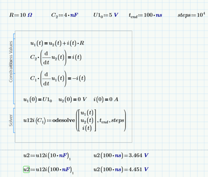
Here in Prime using correct units (one of the very few advantages of Prime over real Mathcad)
EDIT:
Yes, the definition of C1 at the top can be deleted as the solve block is parametrized.
Furthermore, too retain full formatting capabilities in the plots, you should rather define the range t as follows:
There is hardly a need to use more than 50000 point for a single trace anyway 😉
Prime10 Worksheet attached
EDIT; I made a mistake with the initial condition for i(0). This affects the behaviour in the first 4 ns.
Here is the correct condition:
- Mark as New
- Bookmark
- Subscribe
- Mute
- Subscribe to RSS Feed
- Permalink
- Notify Moderator
For C1 = 100nF:
𝑉𝑏(t = 100𝑛𝑠) ≈ 120.34 V
For C1 = 10nF:
𝑉𝑏(t = 100𝑛𝑠) ≈ 16.97 V
- Mark as New
- Bookmark
- Subscribe
- Mute
- Subscribe to RSS Feed
- Permalink
- Notify Moderator
Not correct for sure... It gives me around for C1=100nF Vb(t=100ns) =4.45V, and for C1=10nF Vb(t=100ns)=3.46V, but not through math calculation. But lets see other opinions...
With your answer like that you are qualified to obtain Nobel prize 😉
- Mark as New
- Bookmark
- Subscribe
- Mute
- Subscribe to RSS Feed
- Permalink
- Notify Moderator
I double checked and now I get:
For C1 = 100nF:
𝑉𝑏(t = 100𝑛𝑠) ≈ 9.28 V
For C1 = 10nF:
𝑉𝑏(t = 100𝑛𝑠) ≈ 0.38 V
But I'm not the expert in this field so let's see other results
- Mark as New
- Bookmark
- Subscribe
- Mute
- Subscribe to RSS Feed
- Permalink
- Notify Moderator
Ok, its not correct nor this second your post, but maybe someone can give a more good answer on this. I am waiting too to see math derivation for this, if someone is able to do
- Mark as New
- Bookmark
- Subscribe
- Mute
- Subscribe to RSS Feed
- Permalink
- Notify Moderator
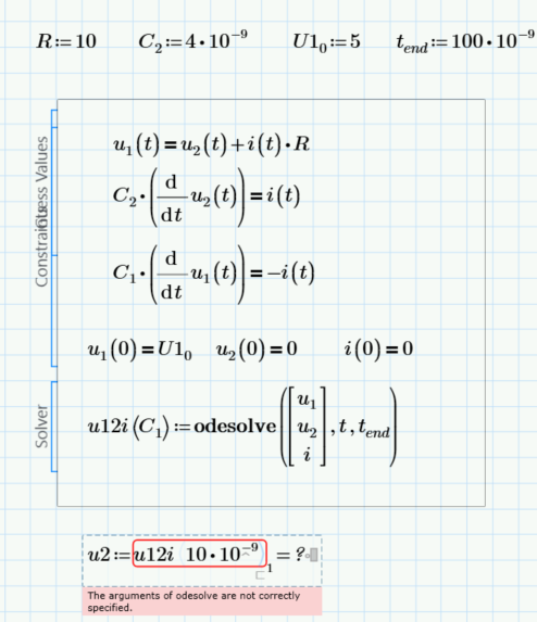
Here numerically in real Mathcad (without units)
- Mark as New
- Bookmark
- Subscribe
- Mute
- Subscribe to RSS Feed
- Permalink
- Notify Moderator
- Mark as New
- Bookmark
- Subscribe
- Mute
- Subscribe to RSS Feed
- Permalink
- Notify Moderator
The syntax of odesolve has changed from real Mathcad to Prime. See the Prime version I posted.
Furthermore you can't numerically evaluate u2! u2 is a function with a single (time) argument and you can use u2 to evaluate it at a specific time value.
- Mark as New
- Bookmark
- Subscribe
- Mute
- Subscribe to RSS Feed
- Permalink
- Notify Moderator
Here in Prime using correct units (one of the very few advantages of Prime over real Mathcad)
EDIT:
Yes, the definition of C1 at the top can be deleted as the solve block is parametrized.
Furthermore, too retain full formatting capabilities in the plots, you should rather define the range t as follows:
There is hardly a need to use more than 50000 point for a single trace anyway 😉
Prime10 Worksheet attached
EDIT; I made a mistake with the initial condition for i(0). This affects the behaviour in the first 4 ns.
Here is the correct condition:
- Mark as New
- Bookmark
- Subscribe
- Mute
- Subscribe to RSS Feed
- Permalink
- Notify Moderator
Can you copy in prime 9 to attached prime 9 sheet?
- Mark as New
- Bookmark
- Subscribe
- Mute
- Subscribe to RSS Feed
- Permalink
- Notify Moderator
Ok, thank you @Werner_E I I succeeded. I am wondering why you put also the value for C1=10nF above the odesolve block? Is needed? I see that is no need to put C1=10nF above odesolve block
- Mark as New
- Bookmark
- Subscribe
- Mute
- Subscribe to RSS Feed
- Permalink
- Notify Moderator
the c1=10mF is a left-over as in my first attempt I had not parametrized the solve block. You sure can delete it now.
- Mark as New
- Bookmark
- Subscribe
- Mute
- Subscribe to RSS Feed
- Permalink
- Notify Moderator
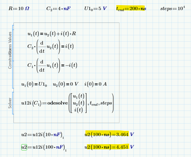
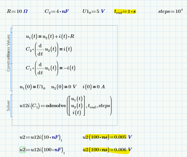
Do you have idea why it is changing the result u2 when changing tend?
- Mark as New
- Bookmark
- Subscribe
- Mute
- Subscribe to RSS Feed
- Permalink
- Notify Moderator
You are using a numeric method to solve your ODEs and if you increase the interval by the factor 5000000 but don't change number of calculations steps, the algorithm also makes steps which are 5 million times larger.
For t.end=200 ns the stepwidth (with steps=10^4) is 0,02 ns but with t.end one step is 10000 ns. So you sure can't expect a meaningful result when you evaluate your functions at t=100 ns because the algorithm has calculated only values for t=0 and t=10000 ns. So for t=100 ns I guess it will just use linear interpolation.
I also don't understand why you want to set t.end to a full second!?
After 400 ns at the latest, everything is over from a practical point of view.
The current is sufficiently close to zero and the voltages have already stabilized to the expected values.
So why look at a longer period of time? This either makes things extremely inaccurate (if you don't increase the number of steps) or unnecessarily slows down the calculation (or may even exhaust memory if steps is set too high).
- Mark as New
- Bookmark
- Subscribe
- Mute
- Subscribe to RSS Feed
- Permalink
- Notify Moderator
I put tend=1 second only to see what's happening, but sure not needed to have such longer period value as plots showed that the current is sufficiently close to zero and the voltages have already stabilized to the expected values after 400/500 ns.
- Mark as New
- Bookmark
- Subscribe
- Mute
- Subscribe to RSS Feed
- Permalink
- Notify Moderator
Could you explain how you came up with these 2 derivation, how do You think about they for u1 and u2:
Not in regard with value, but with expresson as in the form you wrote them as 2 different expression, though they are the same after calculation
- Mark as New
- Bookmark
- Subscribe
- Mute
- Subscribe to RSS Feed
- Permalink
- Notify Moderator
For t-> infinity, the ratio of the decrease of voltage in C1 and increase in C2 is the same as C1:C2 and of course they have to add up to U10.
You can also see in the symbolic solutions (either the one I arrived at with P10 or the one ttokoro posted using Laplace) that the 'end' values for both u1 or u2 are U10*C1/(C1+C2).
- Mark as New
- Bookmark
- Subscribe
- Mute
- Subscribe to RSS Feed
- Permalink
- Notify Moderator
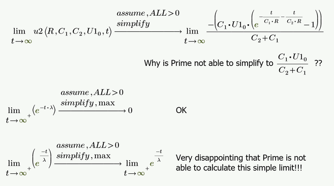
The symbolic in Prime 10 is able to solve the simple simple system symbolically, but only if we omit i(t):
!!!!
It was just now when I compared the plots for i(t) from the solve block and the symbolic solution that i realized that my initial condition for i(0) was wrong!! This failure is responsible for the unnatural behaviour in the first 4 ns.
The correct condition would be i(0s)= U1.0/R which would yield 0,5 A with the given values
!!!!
But Prime fails when it comes to the simple limit t-> infinity. Quite disappointing!
- Mark as New
- Bookmark
- Subscribe
- Mute
- Subscribe to RSS Feed
- Permalink
- Notify Moderator
That's great that symbolliycal solution can be obtained as well. I was wondering for this.
I saw also that strange shape at the beginning in the current plot, and i wanted to ask why looks so, but i see that You figured ouț already that inițial condition for the current was set wrong.
Regarding that second limit where Prime 10 cannot do the calculation I see this also in Prime 9, and my thinking on this is that assume cannot recognize that factor lambda is > 0 when lambda is in the denominație or assume keyword does not work well in this situation. If You put -t/1 then prime will give 0 as the result for that limit. But indeed, i would expected that prime to be able to do also such limit calculation with parameters and with assumptions on parameters, but seems that prime cannot do such thing, indeed bad thing.
- Mark as New
- Bookmark
- Subscribe
- Mute
- Subscribe to RSS Feed
- Permalink
- Notify Moderator
Actually its just a system of two simple ODEs which also could be solved by hand. But its convenient that P10 is able to do so symbolically.
According the limit its not understandable that Prime would respect the assume modifier when I write -lambda*t, but not when we write -t/lambda. Tend to call it a bug.
Here is a very clumsy workaround - two steps are necessary, doesn't work in one go and you sure have to know which result you are striving for (so its quite a useless workaround).
- Mark as New
- Bookmark
- Subscribe
- Mute
- Subscribe to RSS Feed
- Permalink
- Notify Moderator
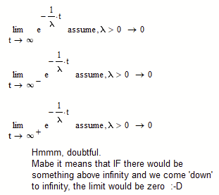
Not very disappointing, but understandable.
How can you let t go to (positive) infinity from above? What is above infinity?
In Mathcad 11:
The error message is: "No symbolic result was found.", and I agree.
But then, the full set of trials is:
I wonder what options Maple considers to not get the limit to 0...
Success!
Luc
- Mark as New
- Bookmark
- Subscribe
- Mute
- Subscribe to RSS Feed
- Permalink
- Notify Moderator
How can you let t go to (positive) infinity from above? What is above infinity?
Touchè ! 🙂
The "+" was a leftover from playing around with the direction of the limit as usually when you use the limit to +- infinity Prime does not care about it.
The disappointing part still is that Prime gives correct results when we use the appropriate "assume" modifier and factor lambda, but not when we use the reciprocal 1/lambda.
Here the results of real Mathcad (V 15 with muPad))
- Mark as New
- Bookmark
- Subscribe
- Mute
- Subscribe to RSS Feed
- Permalink
- Notify Moderator
"I wonder what options Maple considers to not get the limit to 0...":
Well, it must have to with lambda, since:
And I figured that, while being positive, lambda might be so small (near 1/infinity ?) that it counteracts t , but still:
Luc
- Mark as New
- Bookmark
- Subscribe
- Mute
- Subscribe to RSS Feed
- Permalink
- Notify Moderator
This is probably one of the rare cases where in Mathcad the symbolics of muPad (MC14/15) performs better than Maple MC11).
- Mark as New
- Bookmark
- Subscribe
- Mute
- Subscribe to RSS Feed
- Permalink
- Notify Moderator


