
Turn on suggestions
Auto-suggest helps you quickly narrow down your search results by suggesting possible matches as you type.
Showing results for
Please log in to access translation
Turn on suggestions
Auto-suggest helps you quickly narrow down your search results by suggesting possible matches as you type.
Showing results for
Community Tip - Did you know you can set a signature that will be added to all your posts? Set it here! X
Translate the entire conversation x
Please log in to access translation
Options
- Subscribe to RSS Feed
- Mark Topic as New
- Mark Topic as Read
- Float this Topic for Current User
- Bookmark
- Subscribe
- Mute
- Printer Friendly Page
Filter Characteristics Calculation
Nov 10, 2016
05:01 AM
- Mark as New
- Bookmark
- Subscribe
- Mute
- Subscribe to RSS Feed
- Permalink
- Notify Moderator
Please log in to access translation
Nov 10, 2016
05:01 AM
Filter Characteristics Calculation
Hello,
i want to calculate following filter in series:
LC+RC+LC
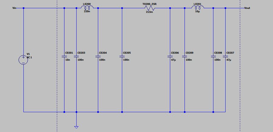
spice simulation result:
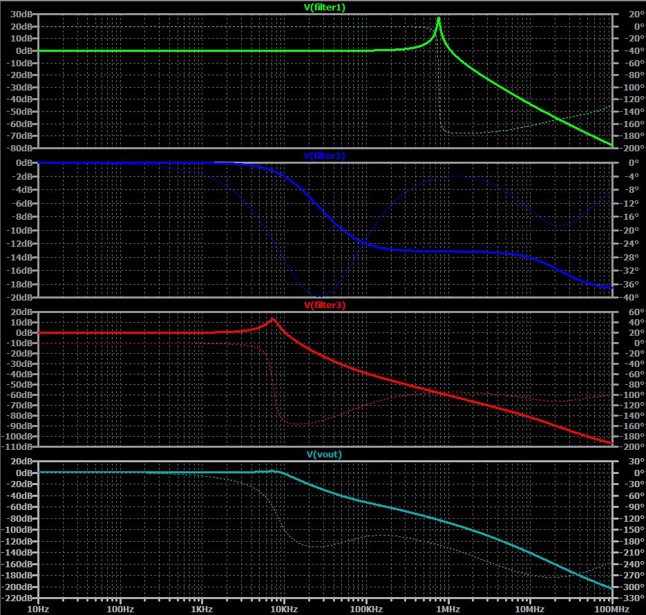
with following transfer functions:
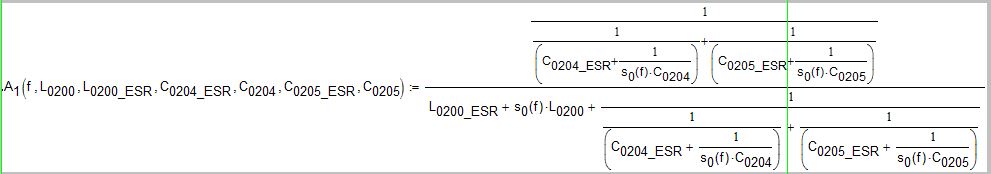
filter1:
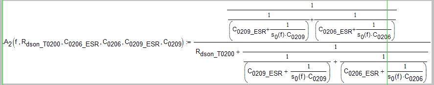
filter2:
filter3:
Could i multiply all three transfer functions in laplace?

As result i get a different magnitude like in spice simulation. Could it be that transfer function of all in series shall calculate in a different way?
Second Question: How can i display the phase without overdue of 180° in the diagram?
Thanks in advance.
Michel
Labels:
- Labels:
-
Other
3 REPLIES 3
Nov 10, 2016
08:51 AM
- Mark as New
- Bookmark
- Subscribe
- Mute
- Subscribe to RSS Feed
- Permalink
- Notify Moderator
Please log in to access translation
Nov 10, 2016
08:51 AM
Hi Michel,
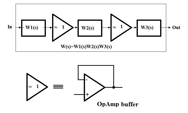
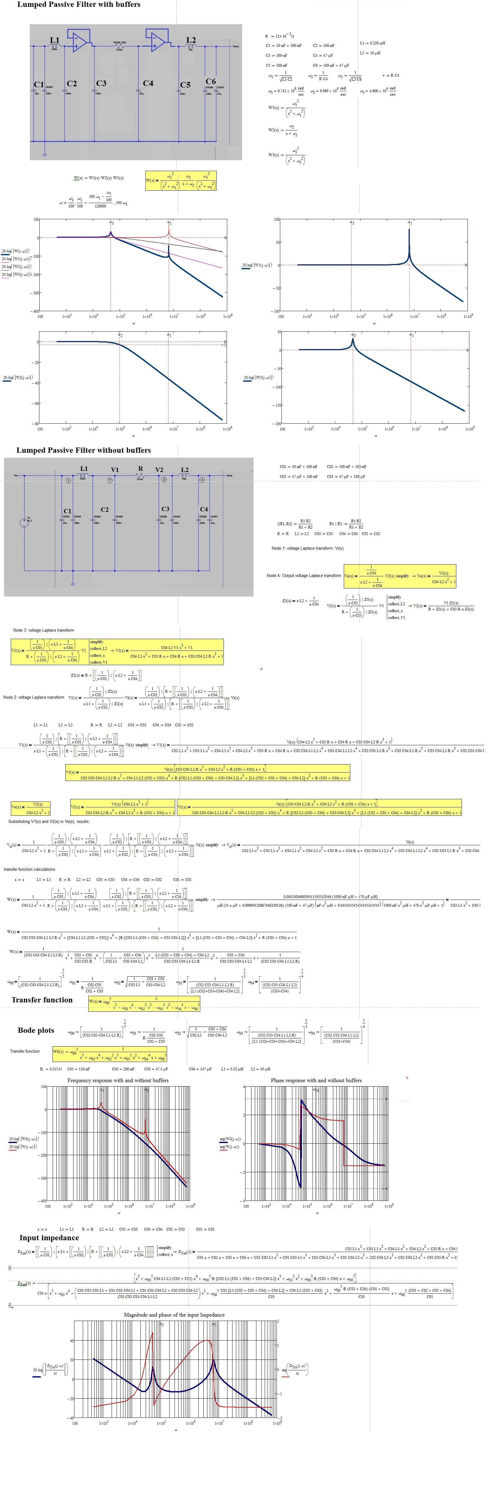
You can't simply multiply the three transfer functions. Doing so, you obtain a transfer function that isn't the one corresponding to three cascaded filters
Insted to obtain a transfer function that is the one corresponding to three cascade filters, you must place a buffer between each filter.
In other words, see the bloch diagram:
Results for R=21.3mOhm
Results assuming R=213m_Ohm:
Nov 10, 2016
09:41 AM
- Mark as New
- Bookmark
- Subscribe
- Mute
- Subscribe to RSS Feed
- Permalink
- Notify Moderator
Please log in to access translation
Nov 10, 2016
09:41 AM
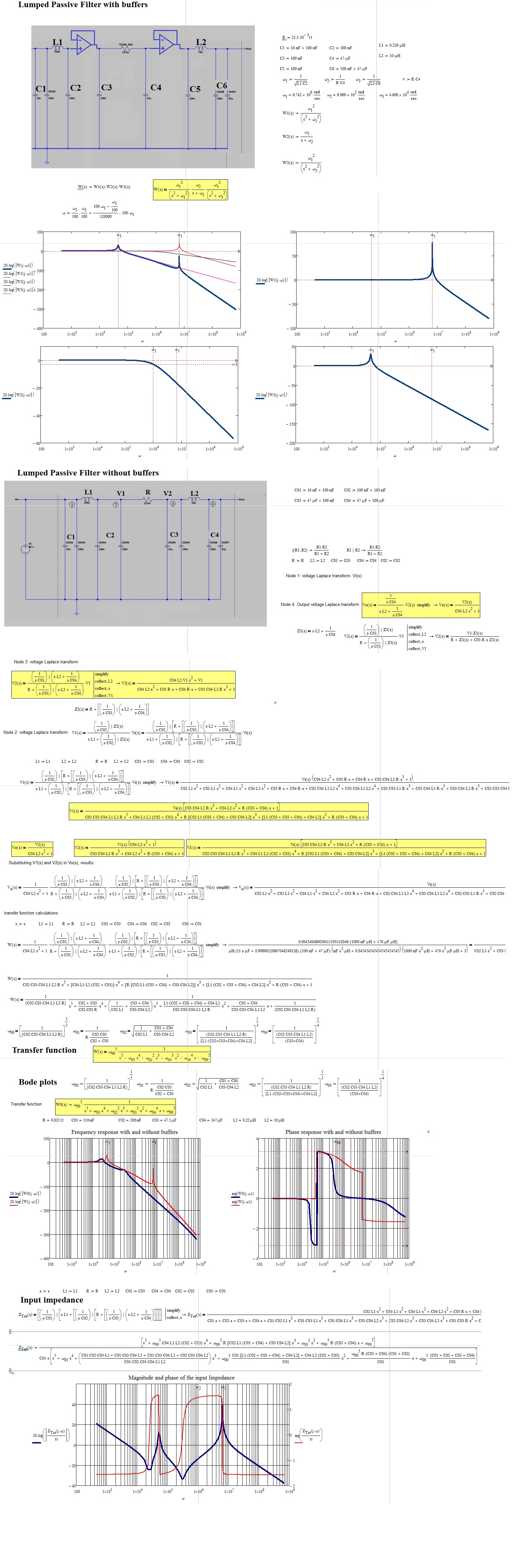
A few initial points:
- the caps directly across the voltage source do nothing for the filter , they simply present an additional load on the voltage source so you can remove them for the analysis of the filter
- to simplify things you should consider the parallel caps as single components
I would normally use a nodal analysis and solve for the various circuit currents using matrices (which is what Mathcad is good at). Here is a useful link to this technique: https://en.wikiversity.org/wiki/Electric_Circuit_Analysis/Mesh_Analysis
Nov 12, 2016
05:12 PM
- Mark as New
- Bookmark
- Subscribe
- Mute
- Subscribe to RSS Feed
- Permalink
- Notify Moderator
Please log in to access translation
Nov 12, 2016
05:12 PM
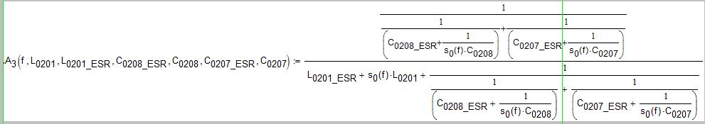
Assuming that the T0200 device shown in your first circuit diagram is a 213 mOhm resistor (you indicate that the middle part of the filter is an RC section), the graphs you provide of the simulation do not match with the behaviour of the circuit. The phase characteristic you have is showing an increase in phase shift from about 12 kHz to 120 kHz. With the circuit as shown the phase only decreases.
In Mathcad the circuit can be analyzed with:

Then:

And we can set:

Which gives:

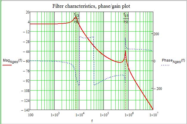
From which the transfer characteristic is found with:

giving:

Now we can plot:

Success!
Luc


