
Turn on suggestions
Auto-suggest helps you quickly narrow down your search results by suggesting possible matches as you type.
Showing results for
Please log in to access translation
Turn on suggestions
Auto-suggest helps you quickly narrow down your search results by suggesting possible matches as you type.
Showing results for
Community Tip - You can subscribe to a forum, label or individual post and receive email notifications when someone posts a new topic or reply. Learn more! X
Translate the entire conversation x
Please log in to access translation
Options
- Subscribe to RSS Feed
- Mark Topic as New
- Mark Topic as Read
- Float this Topic for Current User
- Bookmark
- Subscribe
- Mute
- Printer Friendly Page
Mathcad Community Challenge November 2023 - Mechanical Engineering
Oct 31, 2023
11:17 PM
- Mark as New
- Bookmark
- Subscribe
- Mute
- Subscribe to RSS Feed
- Permalink
- Notify Moderator
Please log in to access translation
Oct 31, 2023
11:17 PM
Mathcad Community Challenge November 2023 - Mechanical Engineering
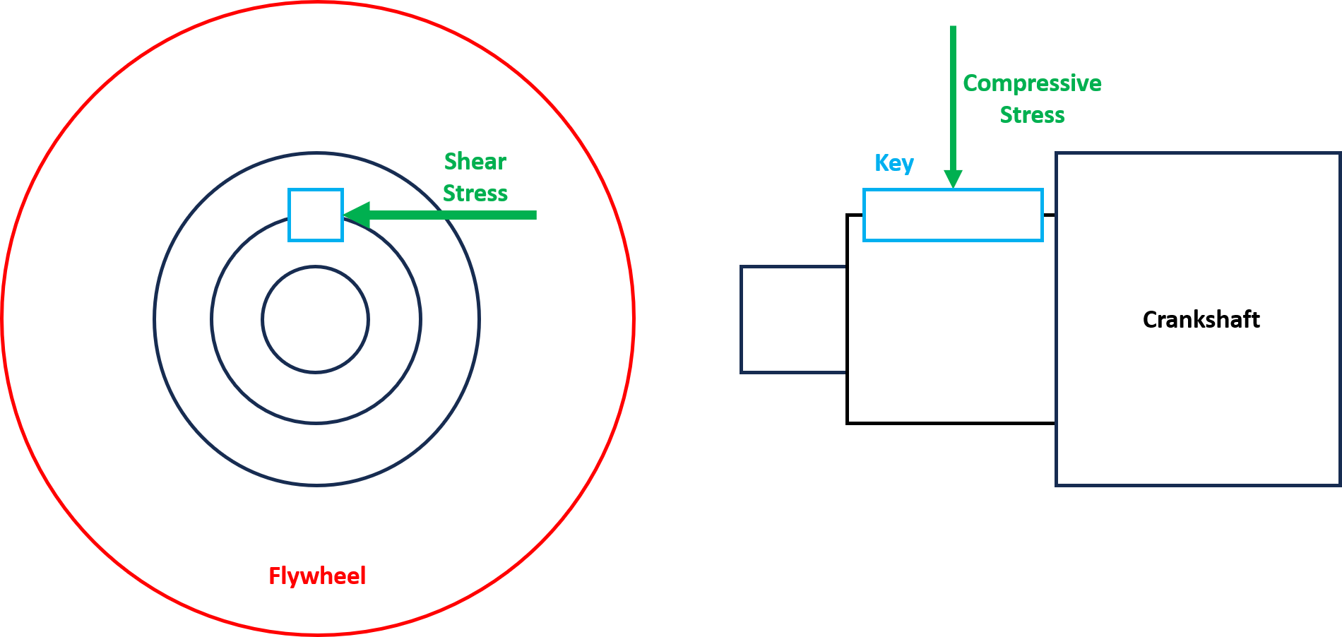
This month’s challenge ties into the Mathcad for Mechanical Engineers Webinar. Your challenge, should you choose to accept it, is to create a worksheet that calculates the stresses on a key in a keyway for a crankshaft and flywheel.
The Scenario
A key is a mechanical component used to transfer power between a rotating shaft and a machine component (in the image below, a flywheel). The torque is 150 Newton-meters.
The shaft diameter where the flywheel is attached has a diameter of 50mm. The key length is 50mm with a breadth (width) of 12.5 mm and total height of 10 mm. The size of the chamfers on the key is 1 mm, but you can ignore them for the stress calculations if you wish.

The Challenge
Your task is to calculate the following:
- Calculate the torque that can be transmitted by the reduced shaft diameter (the diameter not including the keyway).
- Calculate the shear stress and compressive stress on the key and shaft.
- (Optional) Using the technique presented by Dr. Heffernan in this video, include a simple image of the shaft and key with a transparent background. The image does not have to be to scale. The transparent background is the important part.
- (Optional) Create a Chart Component or X-Y Plot of the shear stress as function of the breadth / width of the key. (Or for more intuitive communication, plot the ratio of shear stress relative to the yield strength in shear as a function of the key . (Assume that the material fails in shear at half the nominal yield strength.)
- (Optional) Use Combo Boxes, Tables, Matrices, or other methods to turn this into a “working” worksheet, where users can select different materials, design factors, torque cycles, or other factors of your choosing.
Assumptions
- The components are made of steel (assume a yield strength of 250 MPa).
- Assume that the depth of the keyface between the key and shaft is half the height, but if you want to use the more complicated calculation involving the shaft radius and chamfer size, feel free to do so.
- For the design factor, assume a fixed / close fit keyway.
- For the application factor, assume a uniform load and a uniform power source (in other words, a factor of 1).
- For the fatigue life factor, assume 10 million unidirectional torque cycles.
As always, you should create a worksheet that stands on its own. Judging is based not just on your answers but how you communicate this information to someone picking up the worksheet for the first time. Aesthetics matter.
References
https://calculator.academy/shaft-torque-calculator/ for a shaft torque calculator
https://www.engineersedge.com/mechanics_machines/cylindrical_shaft_moment_of_inertia_13119.htm for moments of inertia
http://steeljis.com/roymech/keyways/key_strength.php (This page has everything you need for the shear stress and compressive stress, but could benefit from Mathcad’s real math notation.)
https://calcdevice.com/torsion-of-shaft-with-keyway-id211.html
https://www.engineersedge.com/calculators/shaft_keyway_shear_and_yield_strength_15867.htm
Find the Mathcad Community Challenge Guidelines here!
Dave Martin - dmartin@creowindchill.com - https://www.mcaeconsulting.com
Labels:
- Labels:
-
Mathcad Challenge
-
Puzzles Games
12 REPLIES 12
Nov 20, 2023
02:16 PM
- Mark as New
- Bookmark
- Subscribe
- Mute
- Subscribe to RSS Feed
- Permalink
- Notify Moderator
Please log in to access translation
Nov 20, 2023
02:16 PM
Reminder to y'all that November is one of those months with only thirty days in them, and it's November 20 now.
I manage the Creo and PTC Mathcad YouTube channels for PTC, as well as all PTC Mathcad marketing in general.
Nov 21, 2023
10:00 AM
- Mark as New
- Bookmark
- Subscribe
- Mute
- Subscribe to RSS Feed
- Permalink
- Notify Moderator
Please log in to access translation
Nov 21, 2023
10:00 AM
Given the lack of responses, I will start posting my worksheets and solutions. This first one shows the torque for the reduced shaft diameter. People can check my work and build on it if desired. I will add more if necessary; maybe I will end up awarding myself the prize for this month's challenge!
Dave Martin - dmartin@creowindchill.com - https://www.mcaeconsulting.com
Nov 24, 2023
04:31 PM
- Mark as New
- Bookmark
- Subscribe
- Mute
- Subscribe to RSS Feed
- Permalink
- Notify Moderator
Please log in to access translation
Nov 24, 2023
04:31 PM
Adding the shear and compressive stress calculations.
Dave Martin - dmartin@creowindchill.com - https://www.mcaeconsulting.com
Nov 25, 2023
06:27 PM
- Mark as New
- Bookmark
- Subscribe
- Mute
- Subscribe to RSS Feed
- Permalink
- Notify Moderator
Please log in to access translation
Nov 25, 2023
06:27 PM
Part 3 adds an image with a transparent background. I've also included the PowerPoint file if anyone wants to improve upon it. It's not perfect as I generated it quickly during halftime of the Apple Cup (University of Washington vs. Washington State University).
Dave Martin - dmartin@creowindchill.com - https://www.mcaeconsulting.com
Nov 27, 2023
11:27 AM
- Mark as New
- Bookmark
- Subscribe
- Mute
- Subscribe to RSS Feed
- Permalink
- Notify Moderator
Please log in to access translation
Nov 27, 2023
11:27 AM
Only 4 days left if someone wants to take an alternate approach or build on my work.
I changed my previous worksheet by turning the mathematical expressions for the stress calculations into functions. Then I created a range variable for the width and two Chart Components.
Dave Martin - dmartin@creowindchill.com - https://www.mcaeconsulting.com
Nov 28, 2023
07:57 AM
- Mark as New
- Bookmark
- Subscribe
- Mute
- Subscribe to RSS Feed
- Permalink
- Notify Moderator
Please log in to access translation
Nov 28, 2023
07:57 AM
Dave;
Just an observation-- the sides of the keyway (that react the compressive stress) are slightly less than your calculation:


The shaft perimeter falls away as the width increases. It would be informative to plot compressive stress in the sidewall as a function of key width, Might find an optimum dimension for width/height.
Your example is a good exercise in basic engineering, but it could be a great example of why Mathcad is such a useful tool for engineering design.
Nov 28, 2023
08:14 AM
- Mark as New
- Bookmark
- Subscribe
- Mute
- Subscribe to RSS Feed
- Permalink
- Notify Moderator
Please log in to access translation
Nov 28, 2023
08:14 AM
Fred,
That is true, the height of the sides of the keyway are less than half the height of the key. That's why I wrote the second assumption to keep things easy. If you take a look at the third link in the references section, under Key Capacity (the image on the right), it goes into a much more accurate calculation of the height.
But I often write these challenges so that they do not become a science project or thesis. I aim for people, especially college students, to be able to participate with less than a couple hours of effort. That's why the challenge asks for only three calculations: torque, compressive stress, and shear stress.
People can - and often do - invest considerably more effort, and I applaud them for it. If anyone wants to use the more complicated calculation for height, they've got until Thursday. I agree that if someone could make this a great example for using Mathcad in engineering design.
Dave
Dave Martin - dmartin@creowindchill.com - https://www.mcaeconsulting.com
Nov 28, 2023
09:33 AM
- Mark as New
- Bookmark
- Subscribe
- Mute
- Subscribe to RSS Feed
- Permalink
- Notify Moderator
Please log in to access translation
Nov 28, 2023
09:33 AM
I'd love to see @Fred_Kohlhepp (and/or anyone else) take this last week of November to go above and beyond (or at the standard, too) the problem and show us great things with Mathcad. And then we can show that to the world in return.
You won't fail the challenge for going above and beyond!
I manage the Creo and PTC Mathcad YouTube channels for PTC, as well as all PTC Mathcad marketing in general.
Nov 29, 2023
08:59 AM
- Mark as New
- Bookmark
- Subscribe
- Mute
- Subscribe to RSS Feed
- Permalink
- Notify Moderator
Please log in to access translation
Nov 29, 2023
08:59 AM
My final submission on this challenge. Here I address the last optional part about making this a "working worksheet." I made a couple Combo Boxes for the Design Factor and Fatigue Life Factor. I left the Application Factor as a regular variable as the two Combo Boxes get the point across.
Combo Boxes require an array - a vertical vector with at least two variables. To get around this, I use a couple garbage variables, gar1 and gar2, which are never used again in the worksheet.
I also disabled the calculation for the original two assignments of the safety factors. But changing the factors affect the appearance of the Chart Components, because I have user-defined ranges on the y-axes. Those math regions can be re-enabled so that the chart formatting looks correct. Since they appear lower down on the worksheet, they will override the selections in the Combo Boxes.
Dave Martin - dmartin@creowindchill.com - https://www.mcaeconsulting.com
Nov 29, 2023
02:42 PM
- Mark as New
- Bookmark
- Subscribe
- Mute
- Subscribe to RSS Feed
- Permalink
- Notify Moderator
Please log in to access translation
Nov 29, 2023
02:42 PM
The garbage variables are not necessary. If you just need one single value as return value from a combo box, simply assign it a normal variable, not a vector.


You may either see this behaviour as inconsistent (as you expected that is should be assigned a 1x1 matrix - which throws an error) or you may see it as a piece of convenience 😉
Nov 29, 2023
02:52 PM
- Mark as New
- Bookmark
- Subscribe
- Mute
- Subscribe to RSS Feed
- Permalink
- Notify Moderator
Please log in to access translation
Nov 29, 2023
02:52 PM
Thanks, Werner. That clears up something I've misunderstood since the functionality was introduced. Since I had most commonly seen it with things like material properties, I thought the Combo Box had to be assigned to a vector / array.
Dave Martin - dmartin@creowindchill.com - https://www.mcaeconsulting.com
Jan 04, 2024
03:31 PM
- Mark as New
- Bookmark
- Subscribe
- Mute
- Subscribe to RSS Feed
- Permalink
- Notify Moderator
Please log in to access translation
Jan 04, 2024
03:31 PM
https://www.mathcad.com/en/blogs/community-challenge-mechanical-engineering
Check out Dave's solution blog about his own solution. There's stuff everyone can learn from how he details his own thought process and approaches to the problem.
I manage the Creo and PTC Mathcad YouTube channels for PTC, as well as all PTC Mathcad marketing in general.


