Community Tip - Want the oppurtunity to discuss enhancements to PTC products? Join a working group! X
- Subscribe to RSS Feed
- Mark Topic as New
- Mark Topic as Read
- Float this Topic for Current User
- Bookmark
- Subscribe
- Mute
- Printer Friendly Page
tracing the edge of a cutting tool (toolpath)
- Mark as New
- Bookmark
- Subscribe
- Mute
- Subscribe to RSS Feed
- Permalink
- Notify Moderator
tracing the edge of a cutting tool (toolpath)
I imagine there must be a proper way to do this, but I wasn't able to look up a good (or any) algorithm.
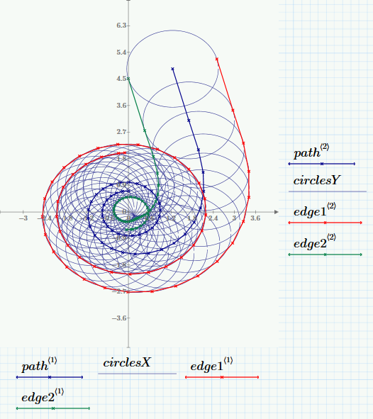
Imagine you're cutting something on a mill. You specify a trajectory for the cutting tool. You're interested in the edges of the tool as it goes along the trajectory. So imagine this tool path with this radius:
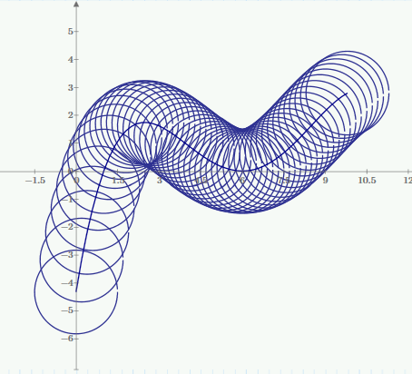
I have come up with a way to trace out the edge by taking derivatives of the trajectory, and then getting points on the circle perpendicular to the slope. I get something like this:
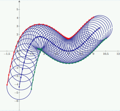
What if I just want the "envelope" of the edges? My edge traces do a loop/wrap-around when there are small turning radii. See what happens to the green edge when it hits the "armpit." The envelope would not include the inner loop.
I had another idea where I can use an image processing approach. So create a black and white image representing the trail of the circles, and then do an edge-find to get the envelope. The pixels can then be translated by to coordinates. I hesitate on this approach as it is not as mathematically "pure."
Thoughts?
- Labels:
-
Calculus_Derivatives
- Mark as New
- Bookmark
- Subscribe
- Mute
- Subscribe to RSS Feed
- Permalink
- Notify Moderator
For each line segment, check if it intersects with any previous line segment. If it does, insert a new point at the intersection, and remove all the points between (but not including) the start of the earlier segment and the end of the later segment.
- Mark as New
- Bookmark
- Subscribe
- Mute
- Subscribe to RSS Feed
- Permalink
- Notify Moderator
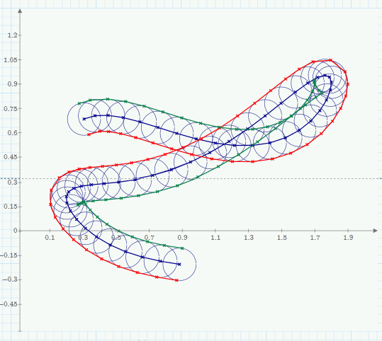
If the trajectory itself is allowed to loop, this algorithm may remove to many points of the path.
How should this case be handled?
- Mark as New
- Bookmark
- Subscribe
- Mute
- Subscribe to RSS Feed
- Permalink
- Notify Moderator
Haha, that's a good point! Let's assume the trajectory doesn't loop. I think that's safe to say for typical machining practices. But this brings up another point. Often times the cutting tool will go in a trajectory where the path will overlap itself. Let's also assume that doesn't happen.
I'm looking into the equations for intersecting line segments:
- Mark as New
- Bookmark
- Subscribe
- Mute
- Subscribe to RSS Feed
- Permalink
- Notify Moderator
Maybe I am misunderstanding what you just wrote, but if you assume the the path will not overlap itself, then you won't have the problem you are trying to solve here anyway!? Don't those summits and loops in those parallel curves of the trajectory arise exactly from an overlapping path?
Another algorithm just comes to my mind, but it sure is not very efficient and probably very slow. First build you green and red paths. Then go along your trajectory and for every point in the trajectory set the coordinates for all points in both paths, which are within a distance of R from the point on trajectory, to NaN. Later use filterNaN() to delete those array elements. Its sort of letting Mathcad play milling machine.
To increase accuracy of the result you may additionally add points on the circumfence of the circle for those line segments where one point is inside and the other outside of the circle.
- Mark as New
- Bookmark
- Subscribe
- Mute
- Subscribe to RSS Feed
- Permalink
- Notify Moderator
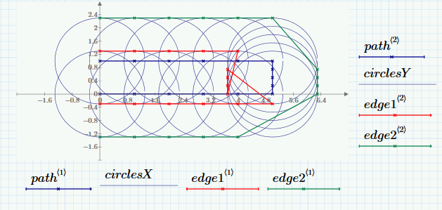
Yeah, I realized that I wasn't being very clear. I was trying to say we can rule out these types of cases:
I actually like your algorithm. It'll be slower than Richard's method (I think), but it'd be easier to code up. For the number of points that I'll be working with, it probably won't be too bad. And I like your milling analogy. Very appropriate!
- Mark as New
- Bookmark
- Subscribe
- Mute
- Subscribe to RSS Feed
- Permalink
- Notify Moderator
I guess my algo would deal with all those cases, too. You just have to takle care of numerical inaccuracies - just use a slightly smaller radius when you delete the points just to be sure that points ON the circle (and every path point would be on at least one circle) will survive.
- Mark as New
- Bookmark
- Subscribe
- Mute
- Subscribe to RSS Feed
- Permalink
- Notify Moderator
A slight modification to what you suggest:
First go along both the red and green lines and check for any intersection with either another segment in the green line, or another segment in the red line. Add points at all those intersections. Any such points that are within the circles will get deleted at the next step anyway, but those that are not will accurately define sharp corners.
- Mark as New
- Bookmark
- Subscribe
- Mute
- Subscribe to RSS Feed
- Permalink
- Notify Moderator
Good idea. I guess every point of intersection will be added twice to the list and at the end both will have survived. So the last phase of the algorithm would be the deletion of those duplicates.
- Mark as New
- Bookmark
- Subscribe
- Mute
- Subscribe to RSS Feed
- Permalink
- Notify Moderator
There is another modification that would improve the accuracy of the final shape a lot. As the paths are built, instead of just adding two points on each side of the path, divide the circle circumference into N equal segments, and add a point for each segment (with the new points of course oriented relative to the path direction just as the current two points are). All thre points on one half of the circle belong to the green line, all the points on the other side belong to the red line. The line will look really ugly before point deletion, and this will slow down the step of deleting points, but the start and end of the tool path, and the tool path for any sharp turns (such as the 90 degree turns in the example above) will be much more accurately represented. The higher N, the more accurate the path, but the slower the algorithm. This could cause weird artefacts if successive circles are too far apart, but if that happens either more circles could be added, or N could be reduced.
Also, instead of marking the points to be deleted as a NaN, it might be faster to delete them on the fly. That way, they don't get checked a second time. The relative speed of the two approaches probably depends on the shape of the path though.
- Mark as New
- Bookmark
- Subscribe
- Mute
- Subscribe to RSS Feed
- Permalink
- Notify Moderator
Good point. Tricky problem ![]()
- Mark as New
- Bookmark
- Subscribe
- Mute
- Subscribe to RSS Feed
- Permalink
- Notify Moderator
Is the problem still vacant?
Attached is just another way to get the paths - no cleaned path yet and no intermediate point for better precison added. I guess this approach using complex numbers might be a bit speedier than calculating and using the angles between the segments. As complex numbers give us in a more natural way an oriented angle between segments it might also be easier to add intermediate point where necessary (on the "outside") - not yet(?) implemented.
Concerning the algorithm to eliminate the "inner" path segments, I begin more and more to dislike "my" brute force approach. Apart from speed I guess it also will remove to much, as the way we construct the path will result just at an approximation of the convex hull and so many points may lie inside the hull and would be errenaously eliminated.
In case its still of concern - I have another approach in mind but I am absolutely not sure if it works for all cases: First I would add half circles at both ends and make one continuous, closed, oriented graph. Then we begin at one arbitrary point and go along the graph until we get a a point where the graph crosses itself. We add that point to the graph (twice) and then we change the branch, that is we ar now going (again in the given direction) at the second part of the crosing branches, coming back later to deal with the other branch (a recursive approach seems adequate here). This we do until we arrive at the starting point. That way we have created a subpath which is closed and lies either completely inside (as will be removed later) or outside. As we always come back to the points of crossing, at the end we will have splitted our path in a couple of closed loops which should either survive completely or ar eto be deleted as a whole. All wee would need now is a reliable way to decide whether a specific partial is to be deleted or not.
Its a pity we don't have pointers and the necessary data structures in Mathcad to create those various chained lists, but it should be doable using various vectors containing just the indices into the data vectors. Unfortunately inserting data points in a matrix is rather time consuming if we use submatrix and stack - we had some threads here that have shown that even self written routines using for-loops are speedier.
Any comments?
BTW, what is the final aim? What would that "cleaned up" path would be used for?
- Mark as New
- Bookmark
- Subscribe
- Mute
- Subscribe to RSS Feed
- Permalink
- Notify Moderator
Then we begin at one arbitrary point and go along the graph until we get a a point where the graph crosses itself. We add that point to the graph (twice) and then we change the branch, that is we ar now going (again in the given direction)
I thought about that yesterday, but I couldn't figure out how to decide which way to go at an intersection. I think I've got it figured out now though. Using your "loop" as an example, at the start of the path, when facing in the direction of travel, the green line is on the "right", and the red line is on the "left" (not exactly a mathematical way of putting it, but I'm after the concept at this point). If we start on the green line then when we get to an intersection we always make a "right turn". This forces the path to be on the outer perimeter, and we will eventually get back to the start. If we start on the red line, we always make a "left turn' at an intersection. So to summarize, if we start on the left we always make make left turns, and if we start on the right we always make right turns.
- Mark as New
- Bookmark
- Subscribe
- Mute
- Subscribe to RSS Feed
- Permalink
- Notify Moderator
My approach would be that the whole path (green and red) is a closed loop - the half circles at the ends close it and that loop has an orientation (= the order in the vector, so one of the two halves has to be reversed before we combine them) . When we come to an intersection, I simply change the path, but I still go in the direction of this orientation. So if I start at point number 0 and arrive at an intersection segment 50-51 crosses segment 200-201, Then the point of intersection is calculated and inserted as point 51 AND as point 202 (old point number 51 is now 52, old 200 therefore gets 201, second new point will be 202). I remember (recursion started) point 51 as the start of a new subpath and continue the current subpath with 202 (the newly added), 203, etc. Eventually we will arrive at the last point of our list (after all we have a vector, not a closed chained list) and should add the starting point as endpoint. The points used should be removed or set to NaN as soon as they are processed, in every case as soon as we arrive at a cross point and start a new recursive call. At least I think so, or better, I feel its more safe to do so.
At the moment I am missing the time to implement it and to be honest I am not fully convinced that it covers all possible paths.
- Mark as New
- Bookmark
- Subscribe
- Mute
- Subscribe to RSS Feed
- Permalink
- Notify Moderator
At the moment I am missing the time to implement it and to be honest I am not fully convinced that it covers all possible paths.
Ditto (for my approach), on both counts. It's an interesting problem, but the main reason it's interesting is that a robust solution is not obvious.
- Mark as New
- Bookmark
- Subscribe
- Mute
- Subscribe to RSS Feed
- Permalink
- Notify Moderator
Hi Gentlemen,
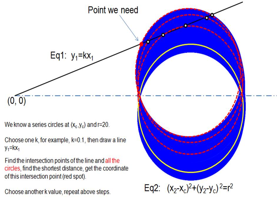
Could somebody help me on solving this? I only need the envelop of the left boundary. I used above methods (see attached), but could not get a correct curve around y=0 when cuting circles were large. I calculated manually like the following picture, and got a reasonable curve. Thanks.
Regards,
Jun
- Mark as New
- Bookmark
- Subscribe
- Mute
- Subscribe to RSS Feed
- Permalink
- Notify Moderator
So why don't you implement your algorithm here and see what you get?
- Mark as New
- Bookmark
- Subscribe
- Mute
- Subscribe to RSS Feed
- Permalink
- Notify Moderator
Because I am a Mathcad beginner. I can not finish it by myself now. I calculated 40 points to get a rough curve. I want to calculate it using Mathcad.
- Mark as New
- Bookmark
- Subscribe
- Mute
- Subscribe to RSS Feed
- Permalink
- Notify Moderator
I see. But the algorithm you propose seems to be not generally applicable for the problem in this thread and it looks like its a very time consuming one. Furthermore you would need a rather dense net of circles to get good results as you algorithm would follow slavishly the segments of the circles and not the milling path itself.
May I ask in which application this problem cam up for you and what you intend to do with the created outline path? In which way you would use it?
- Mark as New
- Bookmark
- Subscribe
- Mute
- Subscribe to RSS Feed
- Permalink
- Notify Moderator
Thanks for your comment, yes, it may be time consuming. It is part of a special joint.
- Mark as New
- Bookmark
- Subscribe
- Mute
- Subscribe to RSS Feed
- Permalink
- Notify Moderator
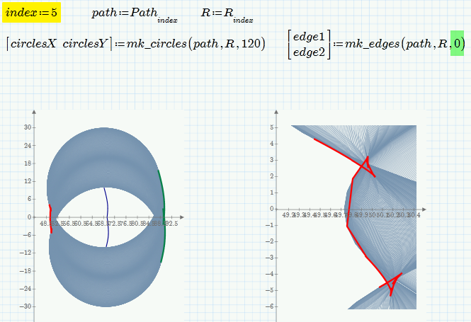
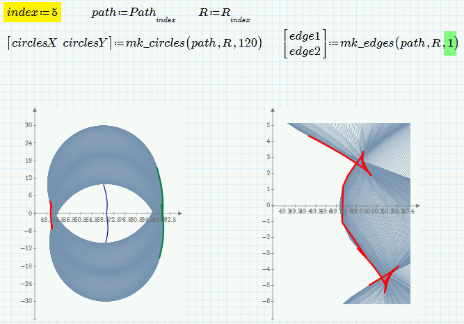
I've modified the file I posted above a bit and the results are not that bad (but far away from perfect). The missing parts are just parts of the circles on both ends which could easily be added. As soon as a stable algorithm is found and implemented which removes the inner cusps, it may even improve.
I was asking about the origin of the problem and the goal to be achieved out of curiosity but also as depending on how the results would/should be used there may be other ways to achieve the desired.
or
- Mark as New
- Bookmark
- Subscribe
- Mute
- Subscribe to RSS Feed
- Permalink
- Notify Moderator
It seems like the problem is a variation of the clipping problem. That is, you start with a boundary and are trying to decide if a new boundary segment is inside, on, crosses, or is outside the exisiting boundary.
If the new boundary is outside, then it is added to the boundary list and all older segments are evaluated to see where they fit. If it is inside, it is rejected. If it crosses, it is clipped to keep the outside segment.
There's a related area of investigation called swept-path analysis. Many of the search results are about getting trucks around street corners and the like.
Of the proposed circle/line algorithm - I've used a variation of that, but just looked for the min value of X for each Y. Even on a little 8MHz (with an M) computer, it was still fast enough, though undoubtedly inefficient. I kept an array with sufficiently small Y deltas (the result was known to intersect the Y-axis) and looked at each horizontal intersection. If X was smaller than Xmin[y] I kept the new value. It won't work for a V path or anything closed.
- Mark as New
- Bookmark
- Subscribe
- Mute
- Subscribe to RSS Feed
- Permalink
- Notify Moderator
I have played around with that problem a little bit (still not implemented an outline algorithm) and thought I would post that intermediate result in case somebody else would like to give it a try despite the fact that neither Roger nor Jun Su seem to show any interest anymore and we therefore don't know what the resulting path should be used for.
I have written the whole thing in Mathcad 15 as this version is far superiour, easier to handle, more convenient and work development is much speedier here. Furthermore a sheet can be converted from MC15 to Prime but not the other way around, so it makes more sense to develop in MC15 from that point of view, too.
What I have done so far is not a big progress. Path datastructure is a vector of complex numbers as this is easier to hande. Path construction is improved by adding points to fill in the gaps and a small routine was added to optionally clean the path from points too close together. A quick attempt to implement the algorithm I proposed failed, but I guess mainly because lack of time and the use of a much too complicated datastructure, trying to implement chained lists and recursive function calls. I think now that it can be done much simpler and without recursion and if I will find some time next week I may give it a second try.
- Mark as New
- Bookmark
- Subscribe
- Mute
- Subscribe to RSS Feed
- Permalink
- Notify Moderator
Great ![]() . When I look at your worksheet, there's loads of red. It seems my licensing is broken, and none of the functions in the extension packs work any more. I bet this is going to be really fun to fix. Not.
. When I look at your worksheet, there's loads of red. It seems my licensing is broken, and none of the functions in the extension packs work any more. I bet this is going to be really fun to fix. Not. ![]()
- Mark as New
- Bookmark
- Subscribe
- Mute
- Subscribe to RSS Feed
- Permalink
- Notify Moderator
Oh, hat sounds bad. I think filterNaN() in my clean_path() routine is the only function I used from those extension packs. So the plots above the call to clean_path should work.
But the only version of Mathcad 15 I know of which is not supporting those extension packs are the academic student single user licenses. All other versions of M15 include those packs automatically, AFAIK.
- Mark as New
- Bookmark
- Subscribe
- Mute
- Subscribe to RSS Feed
- Permalink
- Notify Moderator
I just looked inside the license file, and it says (correctly) that I have permanent licenses for all the extension packs. Maybe a reinstall will fix it, although I'm not overly hopeful of that.
- Mark as New
- Bookmark
- Subscribe
- Mute
- Subscribe to RSS Feed
- Permalink
- Notify Moderator
Strange indeed. And I guess you don't use those extension packs that often and probably can't tell when they worked the last time.
Try to move (not copy) the license file in the licenses directory to a different place, run the license manager and point it to that file. It should get copied in the licenses directory again. I also have my doubts about a full reinstall (but whatever can you try otherwise?)
- Mark as New
- Bookmark
- Subscribe
- Mute
- Subscribe to RSS Feed
- Permalink
- Notify Moderator
Fixed it ![]()
There was no license file at all in the licenses folder ![]() . Not sure how I managed that, but it was probably a causualty of beta testing. Over the years I have switched to temporary licenses more times than I care to think about, and last time I did it I obviously goofed the restore!
. Not sure how I managed that, but it was probably a causualty of beta testing. Over the years I have switched to temporary licenses more times than I care to think about, and last time I did it I obviously goofed the restore!


