Community Tip - If community subscription notifications are filling up your inbox you can set up a daily digest and get all your notifications in a single email. X
- Subscribe to RSS Feed
- Mark Topic as New
- Mark Topic as Read
- Float this Topic for Current User
- Bookmark
- Subscribe
- Mute
- Printer Friendly Page
Phase Plot Error - Bode Diagrams
- Mark as New
- Bookmark
- Subscribe
- Mute
- Subscribe to RSS Feed
- Permalink
- Notify Moderator
Phase Plot Error - Bode Diagrams
Hello,
I encountered a problem with the Bode Diagrams...
How can correct the Phase Plot of the Bode Diagrams for a system which has, for example and simplicity, two poles in origins?
The Phase Plot shows that the system has a +180 degree which is not correct. The system should have a -180 degree.
Thank you.
Solved! Go to Solution.
- Labels:
-
Electrical_Engineering
-
Mathcad Usage
Accepted Solutions
- Mark as New
- Bookmark
- Subscribe
- Mute
- Subscribe to RSS Feed
- Permalink
- Notify Moderator
In electric engineer it is quite customary to have phase plots run continuously, outside of the border of one 'revolution'. A simple fixed delay in time, will produce a continuous phase shift as a function of frequency. This can be tracked, even in Mathcad, to produce a continuous phase plot. BUT it requires prior knowledge in order to track. You have to know the phase shift at one frequency to now how to deal with the phase shift at the next frequency: when it jumps more than 180 degrees either way, you can correct for that by adding or subtracting 360 degrees. Examples of functions that do that are available.
The examples provided by the OP don't allow tracking, becasue the phase shift is the same for all frequencies.
Luc
- Mark as New
- Bookmark
- Subscribe
- Mute
- Subscribe to RSS Feed
- Permalink
- Notify Moderator
The "arg" function will always return values in the range -180° < arg(x) <= 180°. The same applies to the "atan2" function. A phase shift of -180° is equivalent to a phase of +180°.
If you want the "arg"-function to work in a different range (with width 360°) you have to to redefine the "arg"-function to fit your needs.
Using the "arg"-function as defined will always make your phase plot jump if the phase exceeds 180 ° or falls below -180 °.
- Mark as New
- Bookmark
- Subscribe
- Mute
- Subscribe to RSS Feed
- Permalink
- Notify Moderator
But what factor do I need to add to arg(x) to change to the range/width to 0-360 degrees?
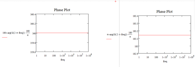
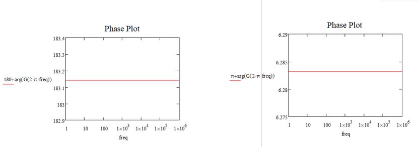
Here is what I'm tried to do:
But yet the results are not satisfactorily:
What am I missing?
Or, what mistake do I do?
- Mark as New
- Bookmark
- Subscribe
- Mute
- Subscribe to RSS Feed
- Permalink
- Notify Moderator
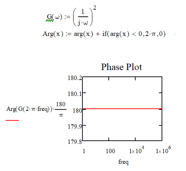
If you want an arg() that returns values from 0 to 2*pi, define e.g.:
Success!
Luc
- Mark as New
- Bookmark
- Subscribe
- Mute
- Subscribe to RSS Feed
- Permalink
- Notify Moderator
Hello Luc,
I tried your variant but things don't seems to change:) (at least in my situation/issue)
Here is the result:
- Mark as New
- Bookmark
- Subscribe
- Mute
- Subscribe to RSS Feed
- Permalink
- Notify Moderator
You wanted an arg() with a result between 0 and 360 degrees (or 0 and 2*pi) . That's what it is...
If you want an arg() that returns -180 instead of 180 (and vice versa) try this:
Success!
Luc
- Mark as New
- Bookmark
- Subscribe
- Mute
- Subscribe to RSS Feed
- Permalink
- Notify Moderator
The idea with arg(x) to be in the range of 0-360 degrees or 0-2pi was suggested by LucMeekes.
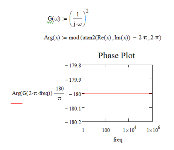
But actually my problem is that I'm trying to make the Bode Diagrams for a simple system that has two poles at origins. The "issue" that arises is in the Phase Plot. I expect to see that the value in the Phase Plot is -90 degree - from one pole + -90 degree - from the other pole = -180 degree - in total. But the graph in Mathcad shows that the value is + 180 degrees, not -180 degrees (the value I would like to see in the graph). And the question is: how can I make the graph (The Phase Plot) to show me the value of -180 degrees, and not + 180 degrees?
I do not know how well you understand what I'm trying to obtain.
If you take a look at the previous Mathcad files I have attached in this topic you may have a better overview.
I understand that arg(x) is defined as the default from -pi to pi. LucMeekes suggested that should I try to change the default definition interval to 0 and 360 degrees or 0 and 2*pi. But if there are other options...are welcome.
- Mark as New
- Bookmark
- Subscribe
- Mute
- Subscribe to RSS Feed
- Permalink
- Notify Moderator
The idea with the change of definition range for arg from -pi<arg(x)<pi to 0<arg(x)<2*pi or 0<arg(x)<360 degrees was suggested by the @LucMeekes in one previous comment of this topic and consequently I said to try this idea as well.
But, again, to resume my issue for a better understanding so as not to deviate from the problem:
I tried to make the Bode Diagrams for a simple system that has double poles at the origins. The problem which I encountered was in the Phase Plot (Magnitude Plot is good). What I expected to see in the Phase Plot from such a system is that the phase should be at -180 degrees and not to +180 degrees as shown in the graph now because one pole produces a phase of -90 degrees and therefore two/double poles produce a phase of -180 degrees phase.
My question was how can make that the graph (Phase Plot) in the Mathcad to show me -180 degrees and not +180 degrees when I have at least double poles at the origins.
Recap:
The characteristic function of the system:
s = j*w;
G1(s) = 1/s;
The system G1(s) has one single pole at the origins, namely: s = 0;
This implies that in the Phase Plot of such a system I want to see a phase of -90 degrees. (For a single pole the Phase Plot in Mathcad looks good)
G2(s) = 1/s^2;
The system G2(s) has double poles at the origins, namely: s1 = s2 = 0;
This implies that in the Phase Plot of such a system I want to see a phase of -180 degrees.
In Mathcad what I see is that the phase is +180 degrees for a system like G2(s). (but it can also be another system which has two double poles. The system of G2 was picked just for the example and simplicity)
Now, whether I change the definition range of arg(x) or anything else, what I want to obtain is that in the characteristic phase of the Bode Diagrams to be able to see a phase of -180 degrees for a system that has at least double poles.
If there are other ideas (and not necessarily redefining the definition range for arg(x)) so that I can achieve this...are welcome.
@Werner_E
- Mark as New
- Bookmark
- Subscribe
- Mute
- Subscribe to RSS Feed
- Permalink
- Notify Moderator
To what extent would a phase of -180 ° be different from one of + 180 ° or + 540 ° or -540 °?
Angles are only unique up to a multiple of 360 °, aren't they?
- Mark as New
- Bookmark
- Subscribe
- Mute
- Subscribe to RSS Feed
- Permalink
- Notify Moderator
In electric engineer it is quite customary to have phase plots run continuously, outside of the border of one 'revolution'. A simple fixed delay in time, will produce a continuous phase shift as a function of frequency. This can be tracked, even in Mathcad, to produce a continuous phase plot. BUT it requires prior knowledge in order to track. You have to know the phase shift at one frequency to now how to deal with the phase shift at the next frequency: when it jumps more than 180 degrees either way, you can correct for that by adding or subtracting 360 degrees. Examples of functions that do that are available.
The examples provided by the OP don't allow tracking, becasue the phase shift is the same for all frequencies.
Luc
- Mark as New
- Bookmark
- Subscribe
- Mute
- Subscribe to RSS Feed
- Permalink
- Notify Moderator
I am aware about the need (or better wish) for continuous phase plots. My point was that a phase of +180° is equally correct than one of -180°. Andrew wrote in his initial post the +180° would NOT be correct.
The need for a continuous plot is understandable, but the example he provided already was continuous - so there was no need to change the phase value from +180° to -180°. He should have provided an example with a sudden jump of the plot (from -179° to 180° for example).
- Mark as New
- Bookmark
- Subscribe
- Mute
- Subscribe to RSS Feed
- Permalink
- Notify Moderator
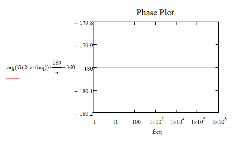
I tried one variant of what you said in the above comment (subtracting 360 degrees).
Here is the result:
Now the question is:
Is this variant/technique correct/valid to apply in any situation or case in Mathcad?
- Mark as New
- Bookmark
- Subscribe
- Mute
- Subscribe to RSS Feed
- Permalink
- Notify Moderator
I understand what both of you (@LucMeekes and @Werner_E) said or suggested. It is correct about analogies between angles.
But there are two premises:
1) From what I've seen so far...all books and most ("all") people not work in that manner (making conversions between angles), when it comes to Bode Diagrams. If a system has double poles at origins (like the simple example I suggested) then I should want to see phase at -180 degrees, and not at + 180 degrees. Indeed, angles are equivalent, but it is unusual to work with them in this way.
2) The example I posted is very simple. Think about what happens when the system becomes complex. Really, I would not necessarily want to make more equivalences and more calculations between degrees or angles because then mistakes and errors can appear faster.
- Mark as New
- Bookmark
- Subscribe
- Mute
- Subscribe to RSS Feed
- Permalink
- Notify Moderator
It sure would have helped if you sent the very specific example you experience problems with.
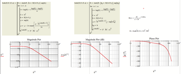
For whatever its worth, here is a quick hack to cope with the problem of the plot jumping up or down at +/- 180 degrees. The reference value is the value of the built-in arg function for the first frequency value. Then going from there a continuous plot is derived. If the arg value of the first frequency is not in the range you are looking for, you would have to redefine the arg function accordingly.
Here is an example with a time delay as mentioned by Luc
And here the result of the bode-function I wrote.
EDIT: I replaced the function I originally posted by two more compact and efficient ones. The variant to the right is based on an idea of LucMeekes 😉
Mathcad 15 Worksheet attached
- Mark as New
- Bookmark
- Subscribe
- Mute
- Subscribe to RSS Feed
- Permalink
- Notify Moderator
I'm a long way from my comfort zone, so maybe I don't understand something.
You have G (or G2 in your later post) defined as (1/j w)^2. This function will have no imaginary part for any value of frequency.
So your phase will always be 180 deg (as shown.)
- Mark as New
- Bookmark
- Subscribe
- Mute
- Subscribe to RSS Feed
- Permalink
- Notify Moderator
But jw is an imaginary part.
Here is the result from Matlab for the system previous posted:
The Phase Plot shows that the system has an -180 degrees phase.
That result is what I what to try to achieve in Mathcad as well.
- Mark as New
- Bookmark
- Subscribe
- Mute
- Subscribe to RSS Feed
- Permalink
- Notify Moderator
This proves NOTHING.
Matlab is a programming language. Your Matlab plots are the results of programming. It is well possible that the routine to calculate the argument of a complex number as implemented in Matlab has a preference for -180 degrees over +180 degrees.
The arg() function in MathCad apparently has a preference for the positive (+180 degrees). And I'd like to stress that mathcad is not alone in this respect. See:
I showed you that it is equally possible to have the other side available in Mathcad.
Luc
P.S. In case you're wondering what happens with your specific example, the reciprocal of the square of an imaginary number:
- Mark as New
- Bookmark
- Subscribe
- Mute
- Subscribe to RSS Feed
- Permalink
- Notify Moderator
I heard someone some time ago that this thing (the Phase Plot can show -180 degrees and not +180 degrees for such systems described by me at the beginning of the post) can be solved in Mathcad, but I do not know exactly how.
That is why I asked.
- Mark as New
- Bookmark
- Subscribe
- Mute
- Subscribe to RSS Feed
- Permalink
- Notify Moderator
I guess a possible way of implementing that is given here: https://community.ptc.com/t5/PTC-Mathcad/Phase-Plot-Error-Bode-Diagrams/m-p/686674#M191783
Success!
Luc
- Mark as New
- Bookmark
- Subscribe
- Mute
- Subscribe to RSS Feed
- Permalink
- Notify Moderator
@Cornel wrote:
I heard someone some time ago that this thing (the Phase Plot can show -180 degrees and not +180 degrees for such systems described by me at the beginning of the post) can be solved in Mathcad, but I do not know exactly how.
That is why I asked.
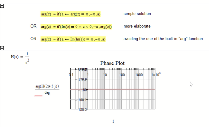
It was already suggested a couple of times - why not redefine the arg function to your needs/wishes?
You may do it in a collapsed region at the top of the worksheet so its out of the way.
- Mark as New
- Bookmark
- Subscribe
- Mute
- Subscribe to RSS Feed
- Permalink
- Notify Moderator
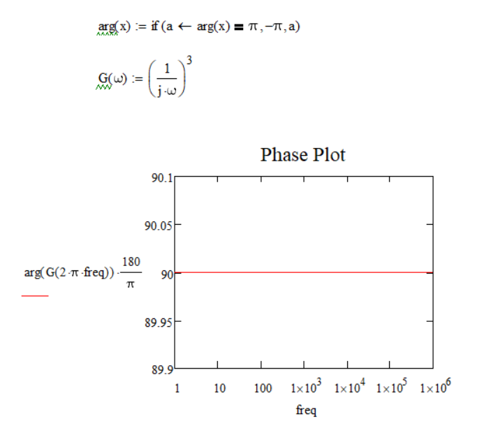
Yes, but that solution only seems to resolve that particular case (i.e. when the transfer function of the system is: G = (1/s)^2).
For example, when the transfer function is: G = (1/s)^3 the plots from Mathcad and Matlab are:
Matlab result:
Mathcad result:
a) With your suggestion:
a) Without your suggestion:
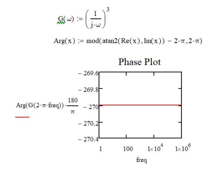
Because now the system has 3 poles at origins, the Phase Plot should have -270 degrees (-90 degrees for the first pole + -90 degrees for the second pole + -90 degrees for the third pole = -270 degrees). which in Matlab I can see that but not yet in Mathcad.
Yes, if you tell me now that -270 degrees are equivalent to 90 degrees, it's correct, but what I want to see is -270 degrees in Phase Plot and not 90 degrees because, as I said earlier, this is the usual manner of thinking and not doing some equivalences or calculations after to get the usual answer that's found in books:).
- Mark as New
- Bookmark
- Subscribe
- Mute
- Subscribe to RSS Feed
- Permalink
- Notify Moderator
- Mark as New
- Bookmark
- Subscribe
- Mute
- Subscribe to RSS Feed
- Permalink
- Notify Moderator
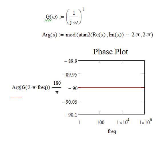
Hm...
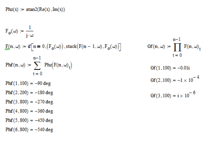
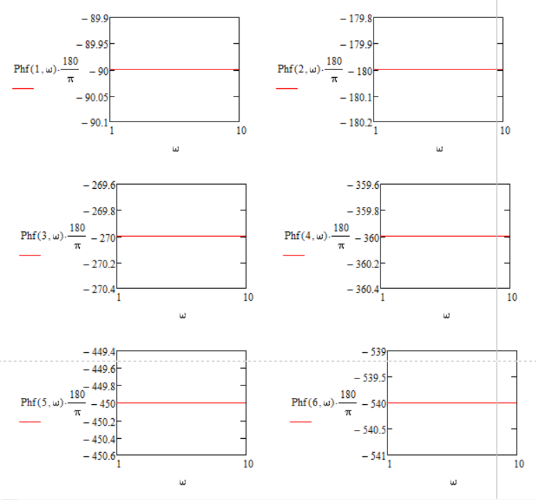
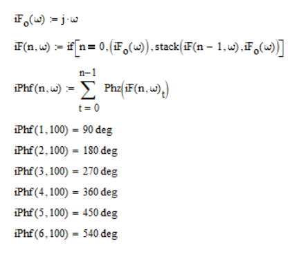
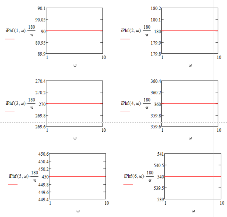
This implementation looks good but still covers only a few particular cases as well as previous suggestions.
For example:
-----------------------------------------
If G = (1/jw)^1
The result is good.
-----------------------------------------
-----------------------------------------
If G = (1/jw)^(-1) = (jw)^1
The result should be +90 degrees.
( I know if you say me now that -270 degrees it's equivalent to +90 degrees (which is correct) then...but my previous comments explain why I do not want more equivalences and further calculations. )
-----------------------------------------
-----------------------------------------
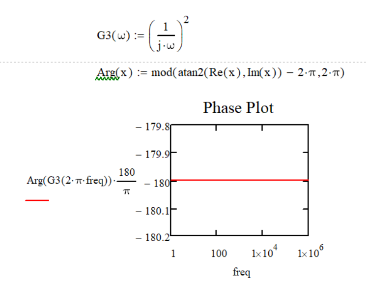
If G = (1/jw)^2
The result is good.
-----------------------------------------
-----------------------------------------
If G = (1/jw)^(-2) = (jw)^2
The result should be +180 degrees.
( I know if you say me now that -180 degrees it's equivalent to +180 degrees (which is correct) then...but my previous comments explain why I do not want more equivalences and further calculations. )
-----------------------------------------
-----------------------------------------
If G = (1/jw)^3
The result is good.
-----------------------------------------
-----------------------------------------
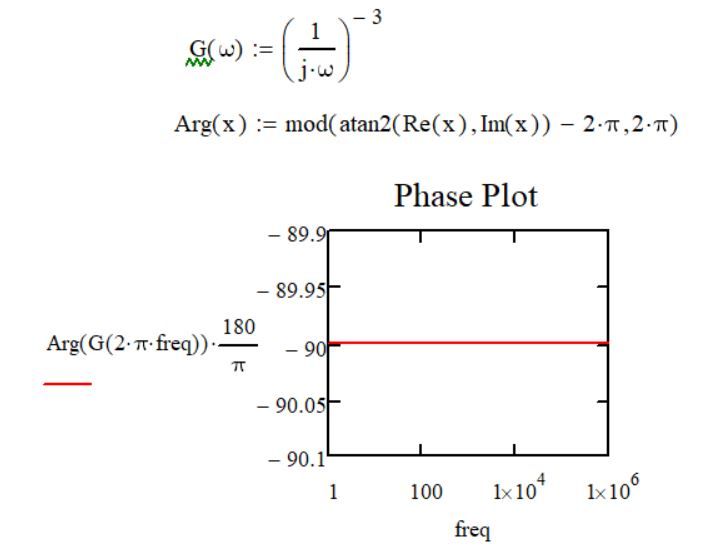
If G = (1/jw)^(-3) = (jw)^3
The result should be +270 degrees.
( I know if you say me now that -90 degrees it's equivalent to +270 degrees (which is correct) then...but my previous comments explain why I do not want more equivalences and further calculations. )
-----------------------------------------
But it's good, it is a step forward your variant.
(Sheet created in Mathcad 15.0 (M50))
- Mark as New
- Bookmark
- Subscribe
- Mute
- Subscribe to RSS Feed
- Permalink
- Notify Moderator
Hm...
Looks good your implementation but still covers some particular cases as well as previous suggestions.
For example:
------------------------------------------------
If G = (1/jw)^2
The result is good.
------------------------------------------------
------------------------------------------------
If G = (1/jw)^(-2) = (jw)^2
The result should be +180 degrees.
Now...If you tell me that -180 degrees are equivalent to +180 degrees...which is correct...but that's not what I am looking for (i.e. furthermore equivalences and more calculations). This I explained in my previous comments.
------------------------------------------------
------------------------------------------------
If G = (1/jw)^3
The result is good.
------------------------------------------------
------------------------------------------------
If G = (1/jw)^(-3) = (jw)^3
The result should be +270 degrees.
Now...If you tell me that -90 degrees are equivalent to +270 degrees...which is correct...but that's not what I am looking for (meaning furthermore equivalences and more calculations). This I explained in my previous comments.
------------------------------------------------
But it's good. It's a step forward.
Thank you for your suggestion/variant.
------------------------------------------------
(Sheet created in Mathcad 15.0 (M50))
- Mark as New
- Bookmark
- Subscribe
- Mute
- Subscribe to RSS Feed
- Permalink
- Notify Moderator
I think this illustrates you problem/challenge:
You cannot mathematically make a distinction between i^2 and (1/i)^2 as they both evaluate to -1, the argument of which is generally pi (or 180 degrees).
Whatever your Matlab examples may show is probably based upon mathematics AND an assumption embedded in the programming code that is used to calculate the argument.
Incidentally, Prime features a (Premium) function phase() that does not have your problem:
As you can see it will never produce pi for an input of (1/i)^2. But also not for i^2 as input. And it will also not produce -pi as an answer. I'm sure you can see how it does that.
I bet the documentation is telling a blatant lie. @Werner_E can check that.
I wonder if the same function is available in Mathcad 15, and also for phasecor()..
Success!
Luc
- Mark as New
- Bookmark
- Subscribe
- Mute
- Subscribe to RSS Feed
- Permalink
- Notify Moderator
phase() and phasecor() are present in MC15, too, as part of the signal processing extension pack.
Either I never was aware of them or I forgot about them.
phase will not help as it returns the very same values as arg and of course you get back 180° for a negative input value.
phasecor() does what I achieved with different methods in the bode() function I posted earlier - tracking the phases an avoiding jumps at +-180°. Reference value is the first phase value like I implemented it, too.
- Mark as New
- Bookmark
- Subscribe
- Mute
- Subscribe to RSS Feed
- Permalink
- Notify Moderator
- Mark as New
- Bookmark
- Subscribe
- Mute
- Subscribe to RSS Feed
- Permalink
- Notify Moderator
- Mark as New
- Bookmark
- Subscribe
- Mute
- Subscribe to RSS Feed
- Permalink
- Notify Moderator
1) This variant only shows that it counts the phase value. But after 360 degrees 0 degrees shouldn't come!?
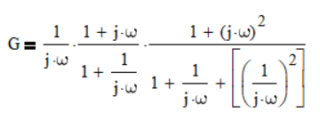
2) The two systems are separate (just for simplicity), but what should I do if I will have a system like this:
Or even more complex...
(Sheet created in Mathcad 15.0 (M50))
- Mark as New
- Bookmark
- Subscribe
- Mute
- Subscribe to RSS Feed
- Permalink
- Notify Moderator


