
Turn on suggestions
Auto-suggest helps you quickly narrow down your search results by suggesting possible matches as you type.
Showing results for
Please log in to access translation
Turn on suggestions
Auto-suggest helps you quickly narrow down your search results by suggesting possible matches as you type.
Showing results for
Community Tip - Did you get an answer that solved your problem? Please mark it as an Accepted Solution so others with the same problem can find the answer easily. X
- Community
- Customer Success
- PTC University LEARN Questions
- Re: Discussion Task
Translate the entire conversation x
Please log in to access translation
Options
- Subscribe to RSS Feed
- Mark Topic as New
- Mark Topic as Read
- Float this Topic for Current User
- Bookmark
- Subscribe
- Mute
- Printer Friendly Page
Discussion Task
Sep 16, 2024
09:12 AM
- Mark as New
- Bookmark
- Subscribe
- Mute
- Subscribe to RSS Feed
- Permalink
- Notify Moderator
Please log in to access translation
Sep 16, 2024
09:12 AM
Discussion Task
I'm really in need of someone's help in completing the discussion task.
I carried it out perfectly at work and had no issues, I thought I'd try it again to confirm my knowledge and now Creo is acting COMPLETELY differently and it's driving me crazy, it's like the app is set up differently.
Solved! Go to Solution.
Labels:
- Labels:
-
Fundamentals of Modeling 1
ACCEPTED SOLUTION
Accepted Solutions
Sep 18, 2024
12:01 PM
- Mark as New
- Bookmark
- Subscribe
- Mute
- Subscribe to RSS Feed
- Permalink
- Notify Moderator
Please log in to access translation
Sep 18, 2024
12:01 PM
No problem, James. We call this "flexing the sketch".
Just an FYI that this tool doesn't work in every case. What I mean is, if dragging the slider causes the geometry to fail at a specific value it'll just stop updating the geometry. Again, as you play around with it more and more you'll get familiar with it. You'll find that the most "delicate" geometry in a Sketch tends to be arcs adjacent to other arcs. You'll be flexing the sketch and suddenly an arc fill flip 180 degrees. But this is good because you'll see what can happen and could give you insight if, say, an Extrude feature that uses that sketch suddenly fails after modifying a dimension.
Regards,
Matt
-------
Matt Huybrecht
Matt Huybrecht
14 REPLIES 14
Sep 16, 2024
09:23 AM
- Mark as New
- Bookmark
- Subscribe
- Mute
- Subscribe to RSS Feed
- Permalink
- Notify Moderator
Please log in to access translation
Sep 16, 2024
09:23 AM
Hello,
Based on the information you provided I am not sure what you are asking - can you please provide some additional info? As in which behaviors are different?
You mentioned that the experience in Creo is completely different, did you use two different versions (one version in the VM and one version locally installed at work?)
Your post and image reference one of the discussion tasks. The discussion slide is framed to get you to think through how you might create the sketch, as there are multiple ways one could approach the sketch. As such, it is not a traditional task in the sense that you follow steps to create the sketch.
Any additional information you can provide to help me understand what you are experiencing will help me be able to assist you.
------
John H. Walker
PTC University
Technical Curriculum Developer
Creo Parametric
Sep 16, 2024
09:38 AM
- Mark as New
- Bookmark
- Subscribe
- Mute
- Subscribe to RSS Feed
- Permalink
- Notify Moderator
Please log in to access translation
Sep 16, 2024
09:38 AM
HI John,
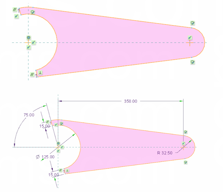
It just seems to be different, the constraints are acting differently and I can't seem to replicate the sketch. it's adding angles and dimensions that I do not want and it's also always displaying in red and I can't get the sketch to show up in the pinkish colour, which to my understanding means that it's a legitimate sketch and it's constrained properly.
I have got as far as the image attached.
Sep 16, 2024
10:05 AM
- Mark as New
- Bookmark
- Subscribe
- Mute
- Subscribe to RSS Feed
- Permalink
- Notify Moderator
Please log in to access translation
Sep 16, 2024
10:05 AM
Thank you for providing the additional info and the image. The pinkish color you are referencing in the training guide is the color used to represent a closed sketch, regardless if there are constraints or not. See an example of a sketch with only one coincident constraint and weak dimensions. The filled in color is only for indicating a closed loop and does not indicate a fully dimensioned and constrained sketch.

My best guess for the discrepancy is one of two things (or both):
- Your company has set their own default colors for closed loop regions and the text. Older versions of Creo used the yellowish color instead of the pinkish color so it's possible that this was modified internally within your company. You can see this info in the "Options" menu found by clicking "file" in the top left.:
- You are using a different version of Creo Parametric. The course content you are using was updated for Creo 10.0 (and it is switching over to Creo 11 today). So some of the UI may look different, but you should be able to constrain the sketch the same.

Based on the image you provided, it seems as if you were able to match the dimensions and constraints of the image in the discussion slide. This leads me to believe, your company has a different customization than the default "out-of-the-box" Creo Parametric install. If you are noting differences like this, focus on the concepts and skills. In this example, if you are able to successfully recreate the sketch and apply appropriate dimensions and constraints, it seems as if you are doing things correctly.
------
John H. Walker
PTC University
Technical Curriculum Developer
Creo Parametric
Sep 16, 2024
10:39 AM
- Mark as New
- Bookmark
- Subscribe
- Mute
- Subscribe to RSS Feed
- Permalink
- Notify Moderator
Please log in to access translation
Sep 16, 2024
10:39 AM
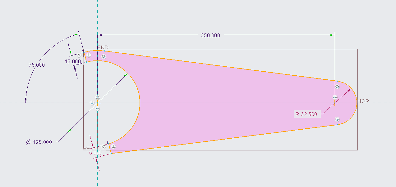
One additional thing you could check is if your theme is different. In the "options" menu, if you are using the "light" theme then your shaded region will appear yellow. If this is the case, you could quickly change to "default" to see if the sketch you created more closely resembles what you were hoping to achieve. See the image below for how changing the them changed the sketch in the image I sent in the previous reply.

------
John H. Walker
PTC University
Technical Curriculum Developer
Creo Parametric
Sep 16, 2024
11:47 AM
- Mark as New
- Bookmark
- Subscribe
- Mute
- Subscribe to RSS Feed
- Permalink
- Notify Moderator
Please log in to access translation
Sep 16, 2024
11:47 AM
HI again,
That's good to know I seem to be doing things right, I can see that a 'custom' system colour setting is applied and it's difficult to get it to stay set to zero, so that might be why. I do have some more questions though if you wouldn't mind answering them.
1. How come my point on entity towards the right of the sketch is horizontal instead of diagonal like in the example?
2. If you look at the axis centre, how come I do not have the two point on entity symbols yet I have two of the centre point symbols?
3. At the top of the sketch I am also missing another point on entity symbol, any reason why?
Thank you for this help, it is genuinely very appreciated.
Sep 16, 2024
04:57 PM
- Mark as New
- Bookmark
- Subscribe
- Mute
- Subscribe to RSS Feed
- Permalink
- Notify Moderator
Please log in to access translation
Sep 16, 2024
04:57 PM
Hello,
The Custom color setting in the Theme happens if you choose a specific theme (Default, Light, Dark) but then further modify any of the individual colors. You can export these colors out (clicking the Export button at the bottom of the dialog) and then setting a config.pro option to point to this exported system colors file (syscol.scl). That will make it such that your colors are retained going forward. Your admin should be able to help you in this regard. Or search for how to do this in the PTC Knowledge base.
Regarding your additional questions:
1. I'm not sure why there is a difference in the constraint "glyph". I assume it's the same constraint but a different version of Creo (this might be a pretty old image from the course). When I re-created this sketch my point-on-entity constraint has a horizontal line like yours.
2 and 3 - I've duplicated your sketch:

If you look at both your sketch and my sketch you'll see that there is a weak dimension present on the left side (this is the light blue dimension that says 0.00 that is kind of hidden behind the parallel constraint).
So technically our sketches are not properly constrained. Or they are, but you're letting the system make a decision for you.
The weak dimension notwithstanding, if you cursor over the circular constraints it says "Constraint (Coincident Vertices)". If you select either of those constraints and click the Explain icon (expand the Constrain group and click Explain) the centers of both arcs highlight and the message window says, "Highlighted vertices coincide". If I delete those 2 constraints and apply the Coincident constraint to of the arcs to the vertical and horizontal reference I am able to get the same constraints as what are in the slide. There are 2 sets of these constraints because I made both arcs coincident on both references:

I just recreated the sketch from scratch and this time I got the constraint result like that of the slide image:

The truth is I don't have a good answer for why there are slightly different solutions here. It's very good that you're considering design intent here because these types of constraint differences can definitely influence the geometry outcome if you modify dimensions. In this particular case, however, I'm not sure the geometry result would change at all given the nature of this specific area of constraint.
I suggest reaching out to Technical Support for further questions like these. They will be able to help you better than me.
Regards,
Matt Huybrecht
-------
Matt Huybrecht
Matt Huybrecht
Sep 17, 2024
03:14 AM
- Mark as New
- Bookmark
- Subscribe
- Mute
- Subscribe to RSS Feed
- Permalink
- Notify Moderator
Please log in to access translation
Sep 17, 2024
03:14 AM
Thanks Matt.
That's very helpful.
Thanks to everyone for the help. I think I'm just struggling to take control over the constraints and what each one does.
Sep 17, 2024
04:07 AM
- Mark as New
- Bookmark
- Subscribe
- Mute
- Subscribe to RSS Feed
- Permalink
- Notify Moderator
Please log in to access translation
Sep 17, 2024
04:07 AM
Hi Matt,
Very quickly... the attached image is what I am currently up to, which I believe looks good.
However, how come I need both of the '15.00' dimensions to be constrained perpendicular to the centre arc, if I remove one then the 0.00 offset line shows up as you mentioned in your first post.
A novelty question too... how come you have very bold lines on yours yet mine seem to all be faint.
Thanks.
Sep 17, 2024
12:07 PM
- Mark as New
- Bookmark
- Subscribe
- Mute
- Subscribe to RSS Feed
- Permalink
- Notify Moderator
Please log in to access translation
Sep 17, 2024
12:07 PM
Hello,
By default, Creo will add constraints and dimensions automatically to maintain a fully dimensioned, fully constrained sketch. The system has added that dimension because it has to add it in order to mathematically fully constrain it.
I think the best way for you to figure out why the system added that weak 0.00 dimension is to modify it and see how the sketch updates. For example, I've updated my value to 20, and you can see here what the result is:

There are other ways to constrain/dimension the sketch to remove that 0.00 dimension rather than using the Perpendicular constraint. Alternatively, if you click the Coincident constraint and select the 2 short diagonal lines the system tells you there is a conflict - the conflict occurs because the sketch is now OVER-constrained and you have to tell the system which thing to remove:

So if I now delete the 20 dimension, the system makes the 2 lines Coincident (or in this case, Collinear), and the dimension is no longer needed:

If you know you want both of those lines to always be the same length, then you can remove one of the 15 dimensions and use the Equal constraint to make both lines equal length. Thus, the length of both lines is now controlled by a single dimension:

The goal here is to dimension and constrain your sketches in such a way that the geometry updates predictably when you need to make changes.
Regarding the bold lines, it's probably one of a few different things:
1. I have Lines Anti-Aliasing enabled (File > Options > Options > Entity Display > Lines Anti-Aliasing).
2. My screen grabs are smaller than yours so I'm zoomed out of the model more. This makes the dimensions and constraints larger with respect to the actual sketch (they stay the same size regardless of zoom level) so my lines might appear thicker.
3. You can adjust sketcher geometry line thickness - I can't remember which Creo version they added this enhancement. Mine is set to the default but perhaps your admin changed it in your config.pro. The config option is sketcher_line_width (default value is 1.5), or you can change it in File > Options > Options > Core > Sketcher > Line thickness:

-------
Matt Huybrecht
Matt Huybrecht
Sep 18, 2024
07:22 AM
- Mark as New
- Bookmark
- Subscribe
- Mute
- Subscribe to RSS Feed
- Permalink
- Notify Moderator
Please log in to access translation
Sep 18, 2024
07:22 AM
That's great Matt.
Thank you very much for the effort you have put into your replies, it really helps a lot.
Sep 18, 2024
11:00 AM
- Mark as New
- Bookmark
- Subscribe
- Mute
- Subscribe to RSS Feed
- Permalink
- Notify Moderator
Please log in to access translation
Sep 18, 2024
11:00 AM
You're very welcome! You're thinking about this the right way. The dimensions and constraints you choose can greatly impact your geometry in terms of how it updates when you make changes.
Best practice is to NEVER leave any weak dimensions that the system auto-generates - YOU should be in control of your geometry because you know best how you want it to update. As you continue using Creo you'll pick up on how the system likes to snap constraints (incidentally, this is configurable). Making your sketches exaggerated and then using dimensions and constraints to refine them works well in helping you get what you want.
If you're ever interested in seeing how your sketch will update based on dimension changes, I suggest picking a dimension or dimensions in the sketch and clicking Modify. This will open a dialog box with the each dimension you select. Next to each dimension is a slider:

You can then drag the slider to dynamically increase/decrease the dimension value. This will give you insight into how the geometry will update as you dynamically change those dimensions.
Creo is crazy powerful, but as the saying goes, "With great power comes great responsibility".
Matt
-------
Matt Huybrecht
Matt Huybrecht
Sep 18, 2024
11:14 AM
- Mark as New
- Bookmark
- Subscribe
- Mute
- Subscribe to RSS Feed
- Permalink
- Notify Moderator
Please log in to access translation
Sep 18, 2024
11:14 AM
That's a great way of visualising dimensional changes, I will definitely be using that from now on!
I was playing about with the 0.00 dimension yesterday to see how it was affecting the sketch and I had to keep clicking back and forward to see the differences, I'm so glad that you have made me aware of that feature.
James.
Sep 18, 2024
12:01 PM
- Mark as New
- Bookmark
- Subscribe
- Mute
- Subscribe to RSS Feed
- Permalink
- Notify Moderator
Please log in to access translation
Sep 18, 2024
12:01 PM
No problem, James. We call this "flexing the sketch".
Just an FYI that this tool doesn't work in every case. What I mean is, if dragging the slider causes the geometry to fail at a specific value it'll just stop updating the geometry. Again, as you play around with it more and more you'll get familiar with it. You'll find that the most "delicate" geometry in a Sketch tends to be arcs adjacent to other arcs. You'll be flexing the sketch and suddenly an arc fill flip 180 degrees. But this is good because you'll see what can happen and could give you insight if, say, an Extrude feature that uses that sketch suddenly fails after modifying a dimension.
Regards,
Matt
-------
Matt Huybrecht
Matt Huybrecht
Sep 23, 2024
06:06 AM
- Mark as New
- Bookmark
- Subscribe
- Mute
- Subscribe to RSS Feed
- Permalink
- Notify Moderator
Please log in to access translation
Sep 23, 2024
06:06 AM
Hi @JW_11780190,
I wanted to see if you got the help you needed.
If so, please mark the appropriate reply as the Accepted Solution. It will help other members who may have the same question.
Please note that industry experts also review the replies and may eventually accept one of them as solution on your behalf.
Of course, if you have more to share on your issue, please pursue the conversation.
Thanks,
Catalina
PTC Community Moderator


