- Community
- Creo+ and Creo Parametric
- Analysis
- Re: HOW TO CONDUCT LIFTING LUG ANALYSIS IN PRO-MEC...
- Subscribe to RSS Feed
- Mark Topic as New
- Mark Topic as Read
- Float this Topic for Current User
- Bookmark
- Subscribe
- Mute
- Printer Friendly Page
HOW TO CONDUCT LIFTING LUG ANALYSIS IN PRO-MECHANICA?
- Mark as New
- Bookmark
- Subscribe
- Mute
- Subscribe to RSS Feed
- Permalink
- Notify Moderator
HOW TO CONDUCT LIFTING LUG ANALYSIS IN PRO-MECHANICA?
Hello every one,
I am designing a huge body for which as cast lifting lugs to be provided. though most of the times we use eye bolts the size constraints do not allow me the same. The minimum load to be taken up by a lug is almost 20 MT (self weight of body),
Please help if you can suggest boundry conditions for such a analysis study.
Thanks,
Prasad
- Mark as New
- Bookmark
- Subscribe
- Mute
- Subscribe to RSS Feed
- Permalink
- Notify Moderator
Hi Prasad,
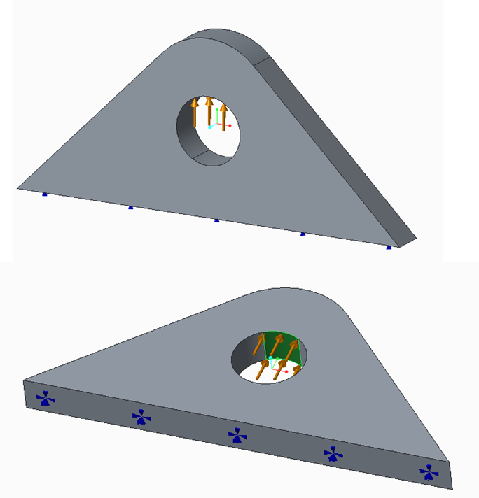
I've seen a type of triangular plate used on large bodies as lifting lugs, though I think they are welded on and not cast. I assume they are easier to cast than a more complicated shape, like a hook or loop. They would look something like the thing shown below. I'd do the following analysis;
1. Do an analysis on the lifting lug shown below, ignoring the larger body thing you are designing. Do a simple fixed constraint on the bottom of the triangle, as seen below. Use a surface region to apply the applied force (from lifting, equal to weight of body), as this is where the strap, cable or chain would be placed. If you know or can guess the width of the cable, even better, as this would better fit the loaded surface area of the hole. This would be a good use of the optimization tool in Creo, or you could do some guess and check to iterate towards a more optimal design. I strongly suspect the optimal shape will look triangular in nature.
2. Once you have the lug roughly designed for the simple case in part #1, do a larger FEA to take into account the effect of lifting on the body. For example, if the body is a large thin walled vessel, its not safe to assume that it will provide a rigid fixed constraint as assumed for part #1. You could apply excessive bending to your vessel wall. Maybe you need to widen the lug to reduce this effect, put more lugs on the vessel, etc.
Its a good general rule to start small and work up, rather than go for the whole thing all at once. Do a free body diagram to be sure you know all the loads and reactions going into the FEA. You should be able to do some simple statics type hand calculation in part #1 to prove to yourself that the answers from FEA are in the right order of magnitude.
I designed a lifting body for an oil & gas cable a couple of years ago. We had to be sure it had a large Factor of Safety on it (4-6), and we had to have a third party test it to 1.5X design load, i.e. tested to 1500 lbs. for a 1000 lbs max working load. If its going to be suspended over someone's head you want to be very sure it won't fall. The point is, when you're doing part #1 analysis you're probably going to want to design for max stress < (yield strength/FOS), and not just max stress < yield strength.
Hope this helps!

- Mark as New
- Bookmark
- Subscribe
- Mute
- Subscribe to RSS Feed
- Permalink
- Notify Moderator
Hello Ron,
You have correctly summerised my problem solution,
I will try routine what you have provided. however as per initial observation this analysis could correctly answer crushing of hole provided for lifting
Will you please shed some light on its effect at contact faces in body or shear or how to simulate that as well in analysis.
As far as my design these lugs will be as cast on the body.
I will post results using routine you have provided.
Kudos,
Prasad
- Mark as New
- Bookmark
- Subscribe
- Mute
- Subscribe to RSS Feed
- Permalink
- Notify Moderator
Hi,
can you post some picture or scheme of what you're talking about?
- Mark as New
- Bookmark
- Subscribe
- Mute
- Subscribe to RSS Feed
- Permalink
- Notify Moderator
Hello Giulio,
sorry for late reply, was on long holiday..
Anyway,
Here is the pic of arrangement
please note cuumulative weight of whole assembly could go up to 50MT although i have done the manual calculations for the same i am particularly looking for same pattern of results in FEA just to be extra sure
Kudos,
Prasad
- Mark as New
- Bookmark
- Subscribe
- Mute
- Subscribe to RSS Feed
- Permalink
- Notify Moderator
I think the procedure that Ron has explained is a good idea.
If you're looking for the stress distribution near a particularly zone you can do a free body analysis, ignoring the rest of the body.
You can use the bearing load instead of the "simple force command".
The welds are ok?


