Community Tip - Did you get called away in the middle of writing a post? Don't worry you can find your unfinished post later in the Drafts section of your profile page. X
- Community
- Creo+ and Creo Parametric
- System Administration, Installation, and Licensing topics
- Re: Creo 4 Config Options - now .csv
- Subscribe to RSS Feed
- Mark Topic as New
- Mark Topic as Read
- Float this Topic for Current User
- Bookmark
- Subscribe
- Mute
- Printer Friendly Page
Creo 4 Config Options - now .csv
- Mark as New
- Bookmark
- Subscribe
- Mute
- Subscribe to RSS Feed
- Permalink
- Notify Moderator
Creo 4 Config Options - now .csv
PTC took my advice to Mike Campbell a few years ago when I told him that the config options should be provided as a spreadsheet.
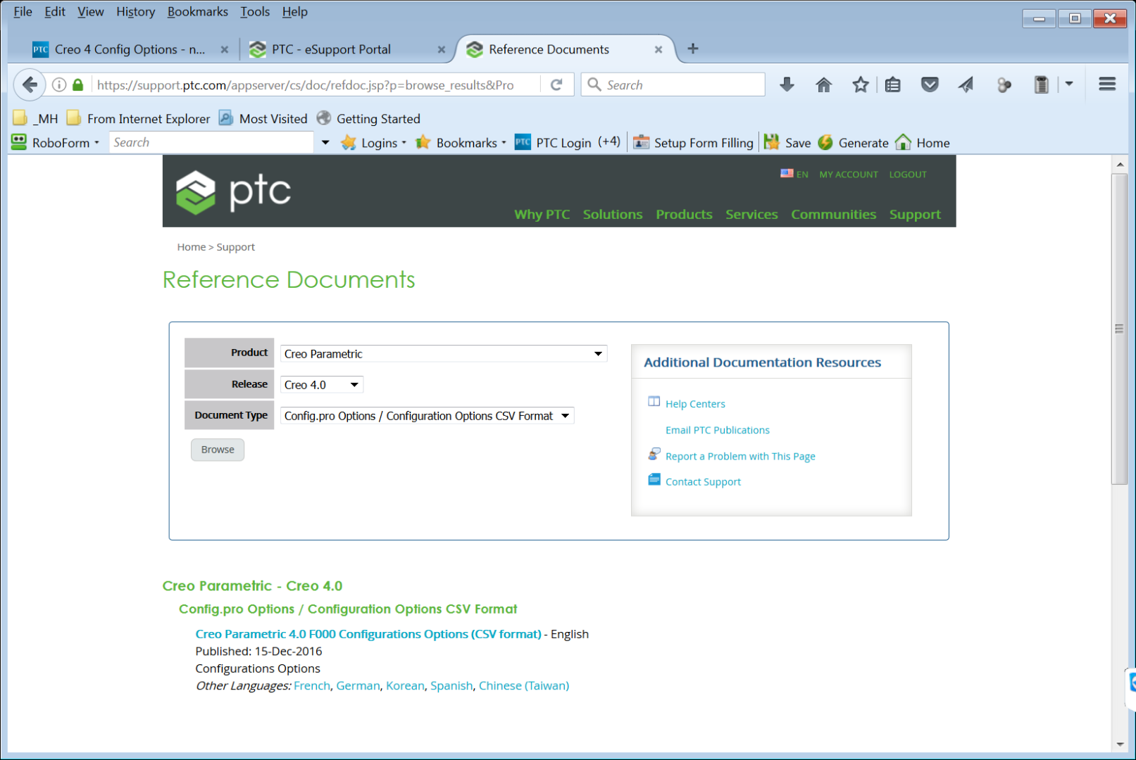
For Creo 4 it comes as a .csv file. I’ve opened it in Excel, Locked the header row, and added two columns on the right for our Creo 3 settings & Creo 4 settings.
I also added filters to the first two columns. See attached.
Solved! Go to Solution.
- Labels:
-
General
Accepted Solutions
- Mark as New
- Bookmark
- Subscribe
- Mute
- Subscribe to RSS Feed
- Permalink
- Notify Moderator
Hi David
I am glad you like the enhancement and thank you for the idea. Please note that Creo 3 and some Creo 2 config csv files have also been created. With every maintenance release we will provide a new csv. Customers will then have the ability to compare the csv file of their current maintenance release against the csv of the maintenance release they are intending to upgrade to.
This should be an easy way to identify new and changed configuration options.
thanks, Jim
- Mark as New
- Bookmark
- Subscribe
- Mute
- Subscribe to RSS Feed
- Permalink
- Notify Moderator
Hi Jim Barrett-Smith,
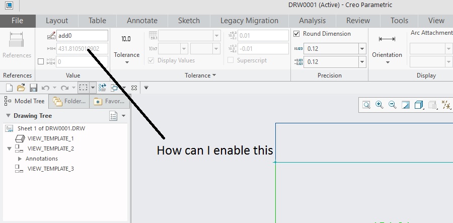
This is screen short of Creo 4.0 drawing. I need to change dimension value such that it automatically changes in part model as well.

Please explain which option do I need to change in config.pro and dtl file to enable this.
Regards
- Mark as New
- Bookmark
- Subscribe
- Mute
- Subscribe to RSS Feed
- Permalink
- Notify Moderator
Good day -
Two Jive tips for you and I hope they are helpful: you mentioned Jim in your comment, the best ways to get another's attion are
- @ Mentioning them. Please type the @ then First Name _ Last Name - for Jim, Jim Barrett-Smith
- If you hover your mouse over a person's name, you will have the option to message that person directly.
Best,
Toby
- Mark as New
- Bookmark
- Subscribe
- Mute
- Subscribe to RSS Feed
- Permalink
- Notify Moderator
Another tipfor Creo Training, you should ask new questions in a new post instead of under another users unrelated post. There are lots of users out there to help and a new question will get the most attention.
- Mark as New
- Bookmark
- Subscribe
- Mute
- Subscribe to RSS Feed
- Permalink
- Notify Moderator
Hi,
you cannot modify value of add0 dimension, because this is driven dimension. The dimension was created in drawing and it does not exists in model.
MH
Martin Hanák
- Mark as New
- Bookmark
- Subscribe
- Mute
- Subscribe to RSS Feed
- Permalink
- Notify Moderator
Please click on above link and watch the video.
After you watch the video then please look at my question and then answer it.
- Mark as New
- Bookmark
- Subscribe
- Mute
- Subscribe to RSS Feed
- Permalink
- Notify Moderator
Taking this tangential question over to it's own thread...
- Mark as New
- Bookmark
- Subscribe
- Mute
- Subscribe to RSS Feed
- Permalink
- Notify Moderator
Martin is correct.
The only dimensions modifiable in the drawing context are those added to the drawing using Show Model Annotations tool.
The label for these dimensions will appear in the ribbon as d#.

-Raphael
- Mark as New
- Bookmark
- Subscribe
- Mute
- Subscribe to RSS Feed
- Permalink
- Notify Moderator
Thanks Raphael,
But please let me know how have you made this 150.00 available for change (I mean its no more grayed out as it is with me)?
Best Regards
- Mark as New
- Bookmark
- Subscribe
- Mute
- Subscribe to RSS Feed
- Permalink
- Notify Moderator
What Raphael is saying is that your dimension can not be changed and will be grayed out because you created the dimension in the drawing.
The 150.00 dimension is shown in the drawing and can be changed and is not grayed out because it is a model dimension that actually controls geometry.
- Mark as New
- Bookmark
- Subscribe
- Mute
- Subscribe to RSS Feed
- Permalink
- Notify Moderator
Hi,
open drawing model (I guess it is a part) in Part mode and modify appropriate feature dimension.
MH
Martin Hanák
- Mark as New
- Bookmark
- Subscribe
- Mute
- Subscribe to RSS Feed
- Permalink
- Notify Moderator
The config options that control the rounding of dimension are covered in the attached document. I don't believe anything has changed since I wrote this back in 2012. But I haven't checked for sure. It's well worth understanding what's happening. If you don't and you manufacture from the model, you could end up with something doesn't fit like you expected.
On the dimensioning issue:
As others have said, you can't do anything with a dimension created in the drawing mode except for rounding it.
I'm wondering if you understand there are two ways to get the dimensions on your part in the drawing mode.
- You can show the existing dimensions that were used to create the features in the modeling mode
- Or you can create dimensions in the drawing.
Generally showing the model mode dimensions is preferred..
- Mark as New
- Bookmark
- Subscribe
- Mute
- Subscribe to RSS Feed
- Permalink
- Notify Moderator
In my experience, we never show dimensions, but rather always create them in a drawing. The main reason why is because the model is always created with deign intent in mind, rather than how it will appear on a drawing using only shown dimensions. The other reason why is because we always employ Top Down Design and therefore the dimensions are rarely if ever there to show if the first place.
- Mark as New
- Bookmark
- Subscribe
- Mute
- Subscribe to RSS Feed
- Permalink
- Notify Moderator
Hello Jim,
where can I find the file, please?
Jan
- Mark as New
- Bookmark
- Subscribe
- Mute
- Subscribe to RSS Feed
- Permalink
- Notify Moderator
- Mark as New
- Bookmark
- Subscribe
- Mute
- Subscribe to RSS Feed
- Permalink
- Notify Moderator
- Mark as New
- Bookmark
- Subscribe
- Mute
- Subscribe to RSS Feed
- Permalink
- Notify Moderator
Since this thread got hijacked for another topic. I'm marking going to mark it resolved.
- Mark as New
- Bookmark
- Subscribe
- Mute
- Subscribe to RSS Feed
- Permalink
- Notify Moderator
Dave,
This looks great. Thank you. I am at Lyncean again.


