Community Tip - Need to share some code when posting a question or reply? Make sure to use the "Insert code sample" menu option. Learn more! X
- Community
- Creo+ and Creo Parametric
- System Administration, Installation, and Licensing topics
- Re: How to add chamfer/round drw notes instances w...
- Subscribe to RSS Feed
- Mark Topic as New
- Mark Topic as Read
- Float this Topic for Current User
- Bookmark
- Subscribe
- Mute
- Printer Friendly Page
How to add chamfer/round drw notes instances within the same feature set
- Mark as New
- Bookmark
- Subscribe
- Mute
- Subscribe to RSS Feed
- Permalink
- Notify Moderator
How to add chamfer/round drw notes instances within the same feature set
Hi,
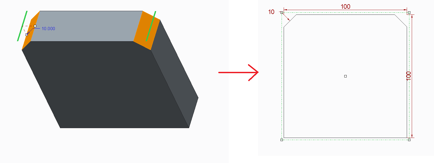
in a part, if I do a chamfer (or round) feature containing just one Set (let's say 10x10) with some edges inside, and If I then go to draft it in a drawing, I find that the note 10x10 is available only once in the Show Model Annotations window. For example, in this case two edges in one set of 10x10, with note on the left chamfer only:

Since it is good practice to make rounds and chamfers with as few sets as possible in the 3D part, but at the same time I would need to have the relative note on all the edges of the Set in the drawing Show Model Annotations, is there an option to set this? (Maybe a config or dtl option?).
(I have searched a thread on this but found nothing, readdressing links would be welcomed of course).
Thanks
Bye
This thread is inactive and closed by the PTC Community Management Team. If you would like to provide a reply and re-open this thread, please notify the moderator and reference the thread. You may also use "Start a topic" button to ask a new question. Please be sure to include what version of the PTC product you are using so another community member knowledgeable about your version may be able to assist.
- Mark as New
- Bookmark
- Subscribe
- Mute
- Subscribe to RSS Feed
- Permalink
- Notify Moderator
The usual practice would be to just add "#X" to the dimension. For instance, in your drawing you would write "2X 10x10 CHAMFER".
If you want to move it, simply left click and edit the attachment in the drawing.
Hope that helps!
- Mark as New
- Bookmark
- Subscribe
- Mute
- Subscribe to RSS Feed
- Permalink
- Notify Moderator
Hi David,
thanks for your reply. Yes it could be done this way in some cases, in some others instead, for example when there are 4 chamfers of which 2 are 10x10 and 2 9x9, I need to label all of them cause by unaided eye they are not distinguishable.
Bye
- Mark as New
- Bookmark
- Subscribe
- Mute
- Subscribe to RSS Feed
- Permalink
- Notify Moderator
In rounds you can create separate sets; each set has it's own radius dimension. I don't recall this to be true for chamfers, but look to see anyway.
It would be valuable, and is unlikely, for Creo to automatically prefix any dimension that drives multiple features through equality or as part of a set with the number of driven items. There are some special cases to deal with, but it would certainly save some trouble if this was true.
- Mark as New
- Bookmark
- Subscribe
- Mute
- Subscribe to RSS Feed
- Permalink
- Notify Moderator
Yes. You can create different sets in a chamfer. Tommaso, I would recommend in the case of multiple sizes of chamfers that you use an annotated dimension rather than using the "show model annotations" option.

- Mark as New
- Bookmark
- Subscribe
- Mute
- Subscribe to RSS Feed
- Permalink
- Notify Moderator
Hi David,
the fact of using multiple load sets (see my last reply to D. Schenken), seems to have drawbacks model performance. Concerning the annotated dimensions, the con would be that I have to put the manually for each of them...
bye
- Mark as New
- Bookmark
- Subscribe
- Mute
- Subscribe to RSS Feed
- Permalink
- Notify Moderator
Hi David,
thanks for your reply. Yes indeed it seems to be true for chamfers too. But the problem of creating many sets with thte same size lays in weigth of the feature itself in the part, thus slowing down regeneration speed for large asseblies: this, at least, is what our Creo trainer told us...suggesting indeed to use as few sets as possible by including all edges with the same round/chamfer size in the same set.
Bye
- Mark as New
- Bookmark
- Subscribe
- Mute
- Subscribe to RSS Feed
- Permalink
- Notify Moderator
When I was a Pro|E drafter/detailer, someone once tried to add the rule "NO MODEL CHANGES BY DRAFTERS"... until they learned how much engineers had to do to manage the other rule "ONLY ASSOCIATIVE (DRIVING) DIMENSIONS ON DRAWINGS"...
Seriously?
There are only a few occasions where I need the driving dimension. In many cases, they do not present as I wish. I threw out the entire cookbook from managers that had nothing better to do that make life miserable for everyone else. They knew very little about CAD but knew a lot about discipline.
This is to say that a Pro|E Detailer MUST go into the model and change some thigns to present correctly on a drawing. I agree that the more driving dimensions that you can use is likely a good thing if you have the discipline to not mess them up when modeling.
In this case, being the engineer, I can see needing multiple sets to detail each feature in the model. Then again, I also see the use of a reference dimension (I use these liberally!) to denote the "odd man out". Most things you can do this in the model, but not radii and chamfers. Similar situations exists when you get into GD&T.
- Mark as New
- Bookmark
- Subscribe
- Mute
- Subscribe to RSS Feed
- Permalink
- Notify Moderator
Hi Antonius,
thanks for your reply.
Yes, the advantage of automatically adding dimensions at the end is in the interest of drafters too, given the fact that they wouldn't be subjected to mistakes...the same reason why associated dimensions are also a strong point for Creo, as far as I experienced.
It's indeed very strange that they don't come out automatically for each edge (for the sake of drawing completeness and clarity), or at least an apposite config.pro setting for activating/deactivating it...so that the user can choose eventually.
I also use reference dimensions directly from the sketcher (with a mapkey to erase the ref. int the drawing), they are useful...but yes, no chance to have them for rounds and chamfers.
Bye
- Mark as New
- Bookmark
- Subscribe
- Mute
- Subscribe to RSS Feed
- Permalink
- Notify Moderator
Hello Tommaso Leati
if l understand correct you key features are following:
1. In 3D models are chamfers driving with 1 dimmensions
2. In drawing are dimmension 5x45° in each chamfer separetly.
-----------------------
Idea:
Create 1 driving chamfer and rest same chmafers creat with COPY and PASTE SPECIAL operations.
See following:
1. Create 1st chamfer als you wish
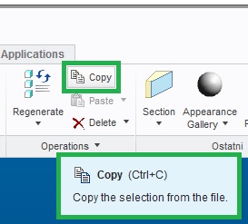
2. Copy 1st chamfer

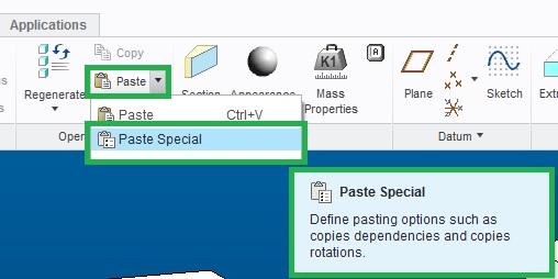
3. Use Paste Special --- Operatin - Paste drop down menu

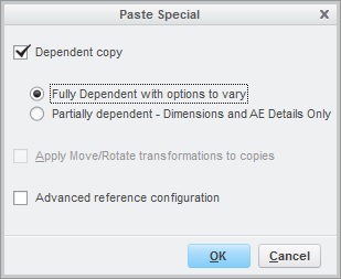
4. Choose "Fully Dependt with options to vary" --- need your investigation --- how does it work exactly ![]()

5. You will create full depend feater
6. Show dimmensions on drawing
----------------------------------------------------------
Model tree is longer, but your problem can be solved with this method.
Don´t have better idea...
Note:
The same method works with hole feature and maybe some other type of features....
Regards
- Mark as New
- Bookmark
- Subscribe
- Mute
- Subscribe to RSS Feed
- Permalink
- Notify Moderator
Hi Milan,
thanks for your reply, could be a way. It creates though many features in the model tree, so it would be heavier for regeneration, at this point maybe it's worth to create separate sets. But it has just one driving dimension and they are all linked together, so for small pieces and assemblies could be done without problems.
Thanks
Bye
- Mark as New
- Bookmark
- Subscribe
- Mute
- Subscribe to RSS Feed
- Permalink
- Notify Moderator
Personally, I would make as many sets (in the same function) as you need to show dimensions. Then constraint equality with relations.
- Mark as New
- Bookmark
- Subscribe
- Mute
- Subscribe to RSS Feed
- Permalink
- Notify Moderator
Have to agree with Raphaël MORIN. It´s other way and also good solution.
What to choose? ---> depends on situation, company habbits/standards etc. ... many ways to go ![]()
- Mark as New
- Bookmark
- Subscribe
- Mute
- Subscribe to RSS Feed
- Permalink
- Notify Moderator
Multiple selections within a single feature will allow much easier access to changes than parent-child copies. If the parent needs to be eliminated the children all require work.
For the truly particular, create a parameter for each size of chamfer and type that name in for the size of the chamfer. It will automatically create a relation and they won't have parent-child relations to worry about.
- Mark as New
- Bookmark
- Subscribe
- Mute
- Subscribe to RSS Feed
- Permalink
- Notify Moderator
David Schenken napsal(a):
Multiple selections within a single feature will allow much easier access to changes than parent-child copies. If the parent needs to be eliminated the children all require work.
Have to agree with David Schenken ... if you need delete parent, than all childerns are getting problems.
From this point of view using relations looks like better solution.
- Mark as New
- Bookmark
- Subscribe
- Mute
- Subscribe to RSS Feed
- Permalink
- Notify Moderator
Hi David,
I hadn't thought about that unconvenient...yes it casts problems with children if the parent is deleted. The fact of the parameter (and then recalling it in the drawing for each chamfer) is quite time consuming and at this point would be maybe faster to pick the edges in the same set and then annotate all of them in the drawing.
Thanks
Bye
- Mark as New
- Bookmark
- Subscribe
- Mute
- Subscribe to RSS Feed
- Permalink
- Notify Moderator
Hi Raphael,
thanks for your reply. Yes, this was the initial idea (and the workaround), if it wasn't for the fact that our ptc trainer suggested us to use just one dirving set for all the edged with same dimension...perhaps for lightening the heaviness of having too many sets...
The same issue of this topic applies to weldings too, by the way. It would be nice to have the weld symbol on all of them.
Bye
Tommaso
- Mark as New
- Bookmark
- Subscribe
- Mute
- Subscribe to RSS Feed
- Permalink
- Notify Moderator
It has been my experience that ptc "trainers" sometimes lack real world experience (not trying to offend anyone). I have seen way too many instances of training that uses poor technique to demonstrate how to use features. They also tend to speak in absolutes (like keeping feature count low) that place too much emphasis on managing the software aspects instead of taking care of the actual engineering of the part. There will always be compromises and trade offs based on the required output and the path to get there.
- Mark as New
- Bookmark
- Subscribe
- Mute
- Subscribe to RSS Feed
- Permalink
- Notify Moderator
Hi Stephen,
yes it may be also, even if in my case, the trainer seemed to be well prepared and he was also working for some companies as an external drafter. Then I recently had the chance to meet a former PTC consultant who was indeed extremely focused on managing skeletons, references, copy geometry...all in order to work in a structured manner...(which pays off anyway at the end). In his opinion, the e-learning module is crap (kept bewteen me, you, and the four walls ![]() ) too. And at this point, the beginner doesn't know which saint to call upon to learn well...
) too. And at this point, the beginner doesn't know which saint to call upon to learn well...![]()
![]() .
.
Bye
- Mark as New
- Bookmark
- Subscribe
- Mute
- Subscribe to RSS Feed
- Permalink
- Notify Moderator
I found it pretty silly to have to hold the Ctrl key to keep chamfers and fillets in the same feature.
Somehow that would have had to surface in the class.
It took me a while to realize that every selection was a new set.


