Community Tip - If community subscription notifications are filling up your inbox you can set up a daily digest and get all your notifications in a single email. X
- Community
- Creo+ and Creo Parametric
- System Administration, Installation, and Licensing topics
- Re: viewres or similar command
- Subscribe to RSS Feed
- Mark Topic as New
- Mark Topic as Read
- Float this Topic for Current User
- Bookmark
- Subscribe
- Mute
- Printer Friendly Page
viewres or similar command
- Mark as New
- Bookmark
- Subscribe
- Mute
- Subscribe to RSS Feed
- Permalink
- Notify Moderator
viewres or similar command
While sketching to create for example an extrusion or revolve, I often have the problem that I'm working in a rather large item (size diameter 8.000mm), and that I have to draw something with size 100mm, tangential to the large object.
In the sketch, the circle or ellipse is visualized as a polygon. But because of the large differences in size, the polygon is very bad approximation.
The drawing will be OK, but it's sometimes annoying to draw a tangential line that doesn't touch visibly.
It would be very interesting to be able to refine the current view, or at least refine the settings and the continue drawing.
Can I do this one way or another?
This thread is inactive and closed by the PTC Community Management Team. If you would like to provide a reply and re-open this thread, please notify the moderator and reference the thread. You may also use "Start a topic" button to ask a new question. Please be sure to include what version of the PTC product you are using so another community member knowledgeable about your version may be able to assist.
- Labels:
-
General
- Mark as New
- Bookmark
- Subscribe
- Mute
- Subscribe to RSS Feed
- Permalink
- Notify Moderator
I have found that a refresh of the graphics will sometimes fix this issue (button on the graphics toolbar).
You can change to higher quality graphics in options but even that is very limited in fixing the problem.
- Mark as New
- Bookmark
- Subscribe
- Mute
- Subscribe to RSS Feed
- Permalink
- Notify Moderator
What part accuracy are you using? by default, Proe & Creo use "relative" accuracy which is basically a ratio between he largest edge and the smallest allowable edge. Switch to absolute accuracy which sets the absolute size the smallest edge can be.
- Mark as New
- Bookmark
- Subscribe
- Mute
- Subscribe to RSS Feed
- Permalink
- Notify Moderator
@Antonius: the refresh button is a very useful button, but almost never it improves the graphic quality. (But I have to say, for some unknown reason, I also noticed an improvement of the graphical quality once or twice by pressing this button)
@Doug: we have changed the accuracy of all our parts to 0.2, sometimes even the minimum absolute value possibe. We have very large parts with very small details. And even now we sometimes reach the limits of the Creo accuracy possibilities.
A good idea for creo would be a button to temporary upgrade the detailing of the screen content, without having to change the global settings.
- Mark as New
- Bookmark
- Subscribe
- Mute
- Subscribe to RSS Feed
- Permalink
- Notify Moderator
There is a technique used in VRML that addresses Level Of Detail (LODs). This is used by PTC as well for graphics performance. It is basically polygon control but should be able to function with wireframe as well.
Over the years, many people have complained about slow graphics performance in Pro|E. PTC has actually done some crude but effective coding to make sessions more responsive. They may have taken it a little too far.
I remember working with pre-wildfire versions where this was not a problem. I don't know what changed exactly, but one of the 1st things I noticed with Creo 1.0 was the very poor wireframe graphics representations in sketched and some other functions.
Sorry, but the only trick up my sleeve was the one button. You might consider opening a support case to see if your particular situation can be resolved in a more effective solution.
- Mark as New
- Bookmark
- Subscribe
- Mute
- Subscribe to RSS Feed
- Permalink
- Notify Moderator
We set our absolute accuracy to 0.0001", or 0.0254mm. Once you have geometry created, Creo will limit the accuracy settings based on the geometry already in place. It's best to set your accuracy in your start part / template before any geometry is in place.
There is a config option "accuracy_lower_bound" that sets the minimum allowable absolute accuracy. I'm not sure what the default is and we do not set this option here, but it may help you.
Also, I've had luck in the past in changing the units of the part, setting the accuracy and then changing the units back. The default that Creo offers is 0.0001, regardless of units, and it will often accept it even if it's below the minimum if you are changing from relative to absolute.
So, change your units to inches, set the accuracy to relative, then set it back to absolute, accepting the default of 0.0001", then change it back to metric. It's a bit of a hack (and may not work any longer in Creo), but has worked for me in the past. It's worth a try.
- Mark as New
- Bookmark
- Subscribe
- Mute
- Subscribe to RSS Feed
- Permalink
- Notify Moderator
Hi Jeroen...
Doug's comment about accuracy_lower_bound should help when you're hitting the minimum allowable accuracy. You can actually set it much lower using this option- but beware there's a performance hit the lwoer you go!
8mm diameter x 100 mm should be possible using some combination of the suggestions given here.
Good luck, please let us know how this worked for you!
Take care..
-Brian
- Mark as New
- Bookmark
- Subscribe
- Mute
- Subscribe to RSS Feed
- Permalink
- Notify Moderator
Hello Jeroen, has Doug's hint helped you? Or did you follow Antonius' suggestion to open a support case? Please let us know, how you went on! And remember to mark answers as helpful or correct (if they are), to maintain the appropriate status of the thread and its posts. Thanks, Gunter
- Mark as New
- Bookmark
- Subscribe
- Mute
- Subscribe to RSS Feed
- Permalink
- Notify Moderator
All ideas posted here are helpful, but do not add anything to what we already knew....
It is something PTC should solve I think.

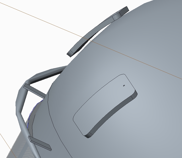
This screenshot shows some of the things we struggle with.
- The reinforcement pad seems to be floating, but in reality the 2 surfaces are coincident.
- The ring around the vessel is circular. But because of the polygon and the strange form, it is sometimes hard to see if the attachment plate is large enough or assembled correctly.
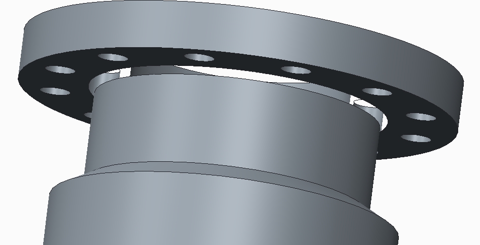
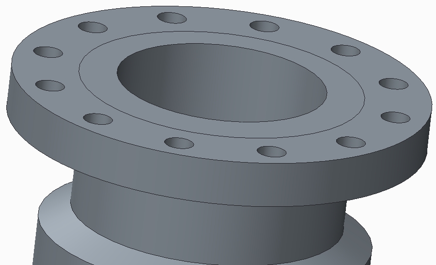
Another example: The nozzles we draw, sometimes get 'visually corrupted'. Nothing wrong with the model itself, but on screen there is something wrong.


These 2 screenshots are from the same nozzle. From below there seems something wrong, you can see through the nozzle. From above, everything seems fine.
This is just a mild occurrence of this problem. We have had some nozzles that disappear completely on screen, although the model is completely there in the model tree. And opening the nozzle by itself shows the correct item.
The only known solution we found is to open the part, edit the definition of the revolve or extrusion, and click on OK without altering anything. After this, the nozzle is ok again (for some time). But sometimes, this will reoccur after some time.
But, for us this story ends...
Due some other issues, difficulties and problems we experience (not only with Creo), we will not continue working with Creo. Our support has allready ended, and will not be extended anymore.
I will not log any case for these questions/problems, I do not have access anymore.
But feel free to use this information to make Creo better!
Thank you all, and farewell!
Jeroen.
- Mark as New
- Bookmark
- Subscribe
- Mute
- Subscribe to RSS Feed
- Permalink
- Notify Moderator
It's sad to hear, that you will abandon Creo, but thank you for sharing this information with us! From looking at the pictures, I believe that the second example is slightly different from the first one: - In the first picture we see inaccuracy caused by very visible tesselation. - However, in the second picture, it sems a small surface (probably chamfer or round) is removed entirely from display. This could be due to the LOD settings or due to a geometry error in the model. If it is LOD settings, then the common song with both examples is: Using low quality display to achieve high performance for spinning and moving. There is a database article about settings that improve performance at the expense of display quality. "Inverting" the settings should generate a vice-versa effect: CS52452 : How to improve performance for large assembly by decreasing display quality in Pro/ENGINEER, Creo Elements/Pro and Creo Parametric http://www.ptc.com/appserver/cs/view/solution.jsp?n=CS52452 Especially options edge_display_quality, shade_quality and skip_small_surfaces (example 2?) sound promising. Gunter


