
Turn on suggestions
Auto-suggest helps you quickly narrow down your search results by suggesting possible matches as you type.
Showing results for
Please log in to access translation
Turn on suggestions
Auto-suggest helps you quickly narrow down your search results by suggesting possible matches as you type.
Showing results for
Community Tip - New to the community? Learn how to post a question and get help from PTC and industry experts! X
- Community
- Creo+ and Creo Parametric
- 3D Part & Assembly Design
- Re: A problem of Double-headed screw
Translate the entire conversation x
Please log in to access translation
Options
- Subscribe to RSS Feed
- Mark Topic as New
- Mark Topic as Read
- Float this Topic for Current User
- Bookmark
- Subscribe
- Mute
- Printer Friendly Page
A problem of Double-headed screw
Jun 17, 2010
11:54 PM
- Mark as New
- Bookmark
- Subscribe
- Mute
- Subscribe to RSS Feed
- Permalink
- Notify Moderator
Please log in to access translation
Jun 17, 2010
11:54 PM
A problem of Double-headed screw
Hi all
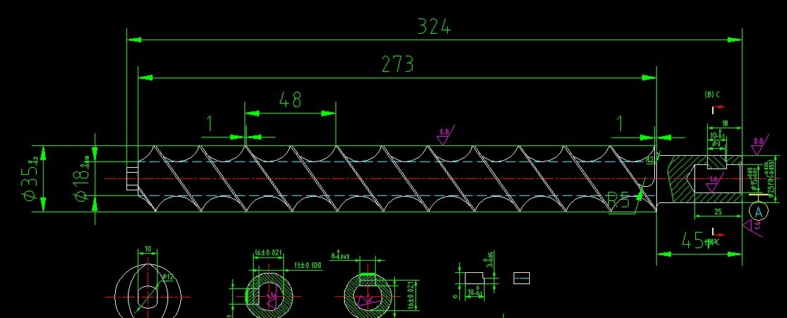
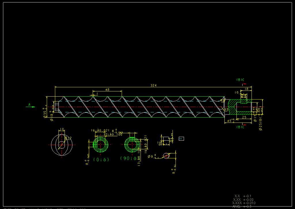
Here is a 2-dimensional drawings.I try to make it into a three-dimensional,
but unsuccessful,
Anybody have experience on this! Plz help me.
This thread is inactive and closed by the PTC Community Management Team. If you would like to provide a reply and re-open this thread, please notify the moderator and reference the thread. You may also use "Start a topic" button to ask a new question. Please be sure to include what version of the PTC product you are using so another community member knowledgeable about your version may be able to assist.
Solved! Go to Solution.
Labels:
- Labels:
-
2D Drawing
ACCEPTED SOLUTION
Accepted Solutions
Jun 18, 2010
02:49 PM
- Mark as New
- Bookmark
- Subscribe
- Mute
- Subscribe to RSS Feed
- Permalink
- Notify Moderator
Please log in to access translation
29 REPLIES 29
Jun 18, 2010
04:02 AM
- Mark as New
- Bookmark
- Subscribe
- Mute
- Subscribe to RSS Feed
- Permalink
- Notify Moderator
Please log in to access translation
Jun 18, 2010
04:02 AM
No one ?
Jun 18, 2010
06:13 AM
- Mark as New
- Bookmark
- Subscribe
- Mute
- Subscribe to RSS Feed
- Permalink
- Notify Moderator
Please log in to access translation
Jun 18, 2010
06:13 AM
Could you tell us, what your problem is exactly ?
Did you not manage this spiraled loft or are you missing functions for it ?
---------------------
SolidDesigner-20.5 + PE8 + PhoenixPDM + Solidworks + Blender
SolidDesigner-20.5 + PE8 + PhoenixPDM + Solidworks + Blender
Jun 20, 2010
11:50 PM
- Mark as New
- Bookmark
- Subscribe
- Mute
- Subscribe to RSS Feed
- Permalink
- Notify Moderator
Please log in to access translation
Jun 20, 2010
11:50 PM
I used with VSS,but unsuccessful.
Jun 18, 2010
02:49 PM
- Mark as New
- Bookmark
- Subscribe
- Mute
- Subscribe to RSS Feed
- Permalink
- Notify Moderator
Please log in to access translation
Jun 20, 2010
11:54 PM
- Mark as New
- Bookmark
- Subscribe
- Mute
- Subscribe to RSS Feed
- Permalink
- Notify Moderator
Please log in to access translation
Jun 20, 2010
11:54 PM
This is what I want. Thanks!
Jun 19, 2010
05:21 PM
- Mark as New
- Bookmark
- Subscribe
- Mute
- Subscribe to RSS Feed
- Permalink
- Notify Moderator
Please log in to access translation
Jun 19, 2010
05:21 PM
Hi Blue_Duncan,
I have a video Tutorial showing one way of modeling the threads. In this toturial, i created a 4X thread Bit. There`s also the Helical function in Proe that may serve its purpose in these kind of situation but i personaly prefer the method illustrated in the video... Here it is: http://www.youtube.com/watch?v=6DdjyF7b8oE
Tell me what you think and good luck.
Jun 20, 2010
09:59 AM
- Mark as New
- Bookmark
- Subscribe
- Mute
- Subscribe to RSS Feed
- Permalink
- Notify Moderator
Please log in to access translation
Jun 20, 2010
09:59 AM
Just tried this method and it works better than the helical sweep. The geometry construction I used tends to cause some slow down when creating the solidify feature.
Jun 26, 2010
01:16 PM
- Mark as New
- Bookmark
- Subscribe
- Mute
- Subscribe to RSS Feed
- Permalink
- Notify Moderator
Please log in to access translation
Jun 26, 2010
01:16 PM
I should add that the method illustrated in the video creats a kind of distorted cut... just like having a Warp feature doing it instead. The cut is not circular. You can see this effect if you increase the amount of turns.
Jun 20, 2010
11:56 PM
- Mark as New
- Bookmark
- Subscribe
- Mute
- Subscribe to RSS Feed
- Permalink
- Notify Moderator
Please log in to access translation
Jun 20, 2010
11:56 PM
I can not link to your website.
Jun 21, 2010
12:42 AM
- Mark as New
- Bookmark
- Subscribe
- Mute
- Subscribe to RSS Feed
- Permalink
- Notify Moderator
Please log in to access translation
Jun 21, 2010
12:42 AM
I can not link to your website.Pass me the video files,please.
Jun 21, 2010
06:38 AM
- Mark as New
- Bookmark
- Subscribe
- Mute
- Subscribe to RSS Feed
- Permalink
- Notify Moderator
Please log in to access translation
Jun 21, 2010
06:38 AM
I cannot attach the video file in the email because its to big so i posted it on rapidshare. Here`s the video download link... try that:
http://rapidshare.com/files/401276735/Bit_tutorialForMCAD.mp4.html
Jun 21, 2010
08:07 AM
- Mark as New
- Bookmark
- Subscribe
- Mute
- Subscribe to RSS Feed
- Permalink
- Notify Moderator
Please log in to access translation
Jun 21, 2010
08:07 AM
Hi,
Its really simple.just click on Autobildz tab in detailing mode.
if your Autobildz tab is not highlighted you need to do some configuration setting
enable_autobildz configuration option.
and see how easy is to create 3D-model from 2D-drawing
Jun 22, 2010
03:33 AM
- Mark as New
- Bookmark
- Subscribe
- Mute
- Subscribe to RSS Feed
- Permalink
- Notify Moderator
Please log in to access translation
Jun 22, 2010
03:33 AM
I do not know how to do what you said.
Jun 21, 2010
04:01 PM
- Mark as New
- Bookmark
- Subscribe
- Mute
- Subscribe to RSS Feed
- Permalink
- Notify Moderator
Please log in to access translation
Jun 21, 2010
04:01 PM
Here are some more files showing some different ways of creating this.
Jun 21, 2010
05:18 PM
- Mark as New
- Bookmark
- Subscribe
- Mute
- Subscribe to RSS Feed
- Permalink
- Notify Moderator
Please log in to access translation
Jun 21, 2010
05:18 PM
Does are very good examples. thanks!
Jun 22, 2010
03:27 AM
- Mark as New
- Bookmark
- Subscribe
- Mute
- Subscribe to RSS Feed
- Permalink
- Notify Moderator
Please log in to access translation
Jun 22, 2010
03:27 AM
You are a warmhearted man 
Jun 25, 2010
03:31 AM
- Mark as New
- Bookmark
- Subscribe
- Mute
- Subscribe to RSS Feed
- Permalink
- Notify Moderator
Please log in to access translation
Jun 25, 2010
03:31 AM
sd5=7.75*360*trajpar How to get the dimension 7.75 ?
Jun 25, 2010
10:50 AM
- Mark as New
- Bookmark
- Subscribe
- Mute
- Subscribe to RSS Feed
- Permalink
- Notify Moderator
Please log in to access translation
Jun 25, 2010
10:50 AM
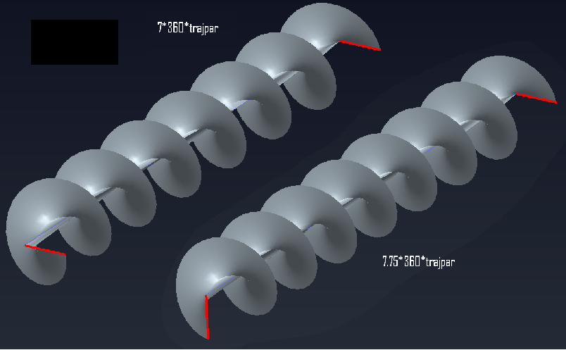
the value 7.75 is arbitrary. It depends on what angle you whant the helical feature to stop at.
For exemple:
for ---7.0 * 360 * trajpar ---
At trajpar = 0 (begining of sweep) the angle reference is zero (7.0 * 360 * 0)
At trajpar = 1 (end of sweep) the angle is still zero (7 * 360 * 0 = 7 full turns, hence zero degree to its original reference)
for ---7.75 * 360 * trajpar ---
At trajpar = 0 (begining of sweep) the angle reference is zero (7.0 * 360 * 0)
At trajpar = 1 (end of sweep) the angle is at 270 degrees (7.75 * 360 * 0 = 7 full turns and 3/4 (270), hence 270 degrees to its original reference)
From what i can assume from Kevin's work is that he wanted the helical sweep to end at a given angle (270 degrees relative to its begining of curve angle)
for some reason i can't put the image directly in this message. I have attached a image illustrating what i'm saying with the exemples
Jun 26, 2010
04:26 PM
- Mark as New
- Bookmark
- Subscribe
- Mute
- Subscribe to RSS Feed
- Permalink
- Notify Moderator
Please log in to access translation
Jun 26, 2010
04:26 PM
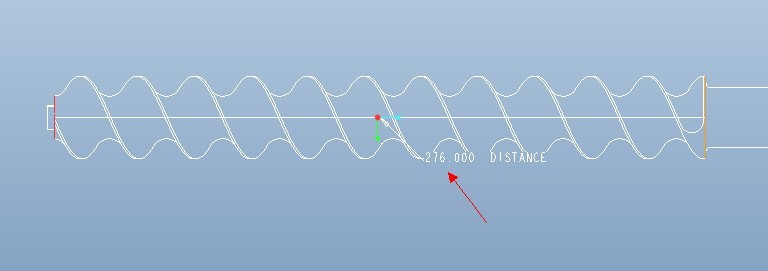
Going back to your original drawing there is enough information that the 7.75 isn't completely arbitrary. Removing the shank length the thread length is 279 (I assume mm). Defining the VSS through the ridge of the first thread and using the lead value you specified on your drawing, the ridge distance of the first thread is 48 mm in one revolution. If you you start at the first ridge the thread length is 278 mm. Dividing 248 by 48 gives 5.792 revolutions. Noticing that the thread doesn't go all the way to the end I chose 5.75 as the number of revolutions which is 276 mm in length. Because of the section I used I needed to extend the sketch for the origin trajectory so the cuts extend through the entire length. I chose to extend the trajectory 1 lead length (48 mm, 1 revolution) at each end so the number of revolutions needs to be 7.75 to make the lead for the screw correct. Another way to do this is to replace the 7.75 in the relation by the length of origin trajectory/lead length which should give the same value and you wont have to worry about updating the value manually if you change the length.
Jun 25, 2010
04:15 AM
- Mark as New
- Bookmark
- Subscribe
- Mute
- Subscribe to RSS Feed
- Permalink
- Notify Moderator
Please log in to access translation
Jun 25, 2010
04:15 AM
Could you make it into a video format? VSS unsuccessful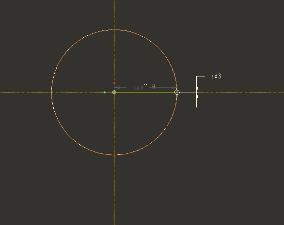
Jun 26, 2010
07:30 AM
- Mark as New
- Bookmark
- Subscribe
- Mute
- Subscribe to RSS Feed
- Permalink
- Notify Moderator
Please log in to access translation
Jun 26, 2010
07:30 AM
Unfortunately I don't have the software required to make a video. For the first VSS (from the picture it looks like that's the one you are refering to), the one used as the X-trajectory, if you have created the section and entered the relation are you getting a flat surface? If so check the options tab and make sure it is set to variable section. Jaques-Michel shows how to create it in his video. The only other thought I have is is that a construction circle or are you using a cylinder surface as a reference? If the latter, it appears you may have additional geometry (two lines) that is preventing a regenerable section. If the end points are at the center and the other on the circle as you have shown in the picture there should only be an angle dimension (sd3).
Jun 27, 2010
08:24 PM
- Mark as New
- Bookmark
- Subscribe
- Mute
- Subscribe to RSS Feed
- Permalink
- Notify Moderator
Please log in to access translation
Jun 27, 2010
08:24 PM
Jun 27, 2010
08:25 PM
- Mark as New
- Bookmark
- Subscribe
- Mute
- Subscribe to RSS Feed
- Permalink
- Notify Moderator
Please log in to access translation
Jun 27, 2010
08:25 PM
Jun 27, 2010
08:28 PM
- Mark as New
- Bookmark
- Subscribe
- Mute
- Subscribe to RSS Feed
- Permalink
- Notify Moderator
Please log in to access translation
Jun 27, 2010
08:28 PM
Wrong 。The original value is 273.
Jun 28, 2010
09:43 AM
- Mark as New
- Bookmark
- Subscribe
- Mute
- Subscribe to RSS Feed
- Permalink
- Notify Moderator
Please log in to access translation
Jun 28, 2010
09:43 AM
I had to make some assumptions because not all the information you show in your pictures came through. When I initially opened the dwg you posted some information is missing when I import the drawing. Here is what I get. The 273 dimension does not show up. Although I could have gotten the dimension by adding a created dimension I didn't think to try that since there was no indication of scale.
Jun 25, 2010
05:42 PM
- Mark as New
- Bookmark
- Subscribe
- Mute
- Subscribe to RSS Feed
- Permalink
- Notify Moderator
Please log in to access translation
Jun 25, 2010
05:42 PM
Kevin,
Could please attach the zipped file again? I could not unzip it. I ge the message that it is part of othe file
Gautam
Jun 26, 2010
04:43 PM
- Mark as New
- Bookmark
- Subscribe
- Mute
- Subscribe to RSS Feed
- Permalink
- Notify Moderator
Please log in to access translation
Jun 26, 2010
04:43 PM
I can upload it again but it will be a couple of days before I can. I did try the files again and had no problems opening them. Another thing you may want to try in the meantime is select the file, right click, and choose explore. This should open the zip file in windows explorer and you should be able to extract the files that way.
Jun 28, 2010
09:50 AM
- Mark as New
- Bookmark
- Subscribe
- Mute
- Subscribe to RSS Feed
- Permalink
- Notify Moderator
Please log in to access translation
Jun 28, 2010
09:50 AM
Here is a new upload to see if you can open.
Jul 14, 2010
01:36 AM
- Mark as New
- Bookmark
- Subscribe
- Mute
- Subscribe to RSS Feed
- Permalink
- Notify Moderator
Please log in to access translation
Jul 14, 2010
01:36 AM
How do I contact you? Can you tell your contact details? Such as MSN account?


