
Turn on suggestions
Auto-suggest helps you quickly narrow down your search results by suggesting possible matches as you type.
Showing results for
Please log in to access translation
Turn on suggestions
Auto-suggest helps you quickly narrow down your search results by suggesting possible matches as you type.
Showing results for
Community Tip - Did you get called away in the middle of writing a post? Don't worry you can find your unfinished post later in the Drafts section of your profile page. X
- Community
- Creo+ and Creo Parametric
- 3D Part & Assembly Design
- Re: Advanced Surfacing Techniques
Translate the entire conversation x
Please log in to access translation
Options
- Subscribe to RSS Feed
- Mark Topic as New
- Mark Topic as Read
- Float this Topic for Current User
- Bookmark
- Subscribe
- Mute
- Printer Friendly Page
Advanced Surfacing Techniques
Sep 14, 2015
04:20 PM
- Mark as New
- Bookmark
- Subscribe
- Mute
- Subscribe to RSS Feed
- Permalink
- Notify Moderator
Please log in to access translation
Sep 14, 2015
04:20 PM
Advanced Surfacing Techniques
Hello to all,
I am new to the PTC CREO world, but I have over 30 years of CAD experience in other softwares and 20 of those 30 years have been all parametric modeling. I am currently using CATIA V5 here at work and I am in the process of evaluating CREO for our engineering department.
So my question is...after importing a surface from CATIA into CREO, where do I go and/or how do I extract the edges of the surface as "curves"?
Labels:
- Labels:
-
Surfacing
35 REPLIES 35
Sep 14, 2015
08:00 PM
- Mark as New
- Bookmark
- Subscribe
- Mute
- Subscribe to RSS Feed
- Permalink
- Notify Moderator
Please log in to access translation
Sep 14, 2015
08:00 PM
Set the selection filter (Lower Right of the screen) to the Geometry.
Select the "edges" you want (hold control if you want multiple)...CNTL C, CNTL V and it will copy them. You can use the tool bar Copy, Paste as well if you prefer that better.
Sep 14, 2015
09:23 PM
- Mark as New
- Bookmark
- Subscribe
- Mute
- Subscribe to RSS Feed
- Permalink
- Notify Moderator
Please log in to access translation
Sep 14, 2015
09:23 PM
Richard,
A second thought crossed my mind in regard to your question. You state you are evaluating Creo but asked how to copy curves in reference to surfacing. Are you looking at converting V5 surfaces to Creo with the same fidelity as the native by copying imported curves? Are you importing simple stuff (ruled, revolved, lofts, blends) or are you copying more complex stuff?
I ask because, while somewhat similar, V5 and Creo have difference methodologies when it comes to some of the deeper stuff.
Sep 15, 2015
08:50 AM
- Mark as New
- Bookmark
- Subscribe
- Mute
- Subscribe to RSS Feed
- Permalink
- Notify Moderator
Please log in to access translation
Sep 15, 2015
08:50 AM
Dean,
Typically when designing a window for a customer my starting point is their referenced OML (outer mold line) surface which is basically the outside surface of the aircraft and a set of curves wihich defines the window opening. From that point I start offsetting the curves along the surface to use as construction geometry for splitting the surface ( a V5 command). This is my methodology in CATIA and also how I would like to generate the same data in CREO. Now this could be considered an advanced surfacing technique in CREO, but any help would be greatly appreciated. The customer's surfaces could be simple or complex depending upon the shape of the aircraft's cockpit.
Sep 15, 2015
09:41 AM
- Mark as New
- Bookmark
- Subscribe
- Mute
- Subscribe to RSS Feed
- Permalink
- Notify Moderator
Please log in to access translation
Sep 15, 2015
09:41 AM
Hi Richard,
I work with both systems and I can tell you that this sort of operation is no problem in Creo.
Admittedly, some 'special' options are somewhat hidden inside curve or surface features but it is all there.
So, creating offset curves along a surface, normal to a surface (both parallel or variable), extending surfaces tangentially, normal or curvature continuous, copying boundaries or curve chains (here Creo actually offers better control about the the chain selection then CATIA, or to put it in other words, getting there with less features like extra points and splits), and everything that is trim (split), or merge (join) related works just as well as in CATIA, just different.
For high end surface creation there is the style feature (a so called super feature which allows you to create free style curves and boundary surfaces 3 or 4 sided) in one feature.
You might want to check the ATB (Advanced Topology Bus) in Creo which allows you to 'smart' import CATIA with the option to update the imported surfaces and curves in Creo if the CATIA model changes.
If you have specific questions about feature comparisons, I am happy to assist.
Sep 15, 2015
10:23 AM
- Mark as New
- Bookmark
- Subscribe
- Mute
- Subscribe to RSS Feed
- Permalink
- Notify Moderator
Please log in to access translation
Sep 15, 2015
10:23 AM
Constantin,
I started playing with PRO/E 2000 and 2001i or something like that, I remember one of them having an 'i'. Back then, I found PRO/E to be difficult and not user friendly like some of the other CAD packages to date so I never really tried to advance my knowledge with it. Now with CREO I find myself with the same mental block as back then...difficult and not user friendly and it could be simply the lack of proper training. I was trying to teach myself back when I worked for Dana Corporation desinging cam/valve covers for Ford, Chrysler and GM.
So which software do you prefer....CATIA or CREO?
I am sure I will be asking a bunch of questions on this forum between now and the end of time.
Sep 16, 2015
03:43 AM
- Mark as New
- Bookmark
- Subscribe
- Mute
- Subscribe to RSS Feed
- Permalink
- Notify Moderator
Please log in to access translation
Sep 16, 2015
03:43 AM
Hi Richard,
I prefer the user interface in Creo (real Creo, not CreoElementsPro AKA Wildfire5) over CATIA V5.
But there are a lot of things in CATIA that I would love to see in Creo. Foremost, working with multi-body parts and all the boolean operations that come with it. Very handy.
Also the advanced surface modules in CATIA are far superior, you can create higher degree surfaces.
At the end of the day I do not really care which one I use. We have both products in the company (and a few more) and we get stuff done with both. It is more a religious question I guess.
Sep 16, 2015
06:36 AM
- Mark as New
- Bookmark
- Subscribe
- Mute
- Subscribe to RSS Feed
- Permalink
- Notify Moderator
Please log in to access translation
Sep 16, 2015
06:36 AM
Constantin,
Agreed, Catia does have the goods with regard to higher order surfaces, and more importantly, control of those higher order surfaces. To be fair, Creo is not a Class A tool...never has been....never will be. Even ISDX cannot do it with 100% confidence. We simply lack the control in the Creo suite for high degree, "verifiable" surface work. We can get close....but not all the way.
The Multi-Body thing I also agree it's a personal preference. We can do it too, with a few more hoops to jump through in Creo.
Cheers
Sep 16, 2015
08:32 AM
- Mark as New
- Bookmark
- Subscribe
- Mute
- Subscribe to RSS Feed
- Permalink
- Notify Moderator
Please log in to access translation
Sep 16, 2015
08:32 AM
Sure....Look at this link for ICEM/Surf
ICEM Surf Surface Modeling - Dassault Systèmes
Catia has this type of ability too. I have not followed Alias in a while so I am not sure if they have added the "math" to the art yet.
So, when I refer to "verifiable" surface work with regard to true Class A modeling, I mean numerically verifiable AND modifiable. Software like ICEM and Catia have the ability not only to report surface quality everywhere but also has the ability to control that "quality" (order/degree) of the surfaces everywhere. And not only at the boundaries (I.E. G2/G3 matching) but also within the boundaries. The biggest "gotcha" the Creo suite suffers from is it's "explicit" nature. It likes to be told what to do. Add to that it's a relatively low order curve driven surface tool which only adds to the mess. Class A software like ICEM has the ability to be told what to do, but can also derive surfaces and morph within the lines via boundary matching.
Also, verifiable means the ability to interrogate the boundaries numerically to deep decimal places. For automotive design, since only one side of the car is surfaced and them mirrored, the centerline deviation accuracy requirement is something like 0.00005". I could have that of by a decimal place but safe to say....it's super critical the centerline is accurate. Not to mention sitting in a surface design review with the Studio Chief interrogating your stuff! Talk about pressure. \('.')/
Remember, we still use full clay models for vehicles (I.E. painted, shiny things that will live in the sunshine). That means we get scan data to use in order to develop the surfaces. Clay is imperfect and we have to "match" it not only per close but also super smoothly. Which means we must have the ability to control the surfaces directly by pulling on nodes (individually, regionally, globally) which is vital to getting good surface work.
Creo has some of this ability over various tools. Freeform has some of the node pulling ability but it's not verifiable and its very limited in scope. Boundary surfaces have the U/V ability but its controlled essentially by curves. ISDX is pretty close and has much better control but still lacks the control AND freedom to build true Class A. Creo Direct has some of the freedom but is governed by the ATB. If I am off on that I am sure I will be corrected. In essence, Direct is digital "clay". Sub-D modeling (Freestyle) is most intriguing to me. It's a whole new animal for the MCAD world (not so for animators) but it could be the wave of the future for surface modeling. I think I am too old to start down that path of mastery.
The Creo suite is, at it's core, an MCAD software. It does it very well and very robustly. It can create some very cool surface models that are, by definition, "complex" and could be described as Class A in the general sense. I.E smooth, flowing, G2, surfaces. But nothing exists in one tool set to do what I refer to as true Class A.
Does that clear or muddy the water?
Sep 16, 2015
09:02 AM
- Mark as New
- Bookmark
- Subscribe
- Mute
- Subscribe to RSS Feed
- Permalink
- Notify Moderator
Please log in to access translation
Sep 16, 2015
09:02 AM
Good point, bringing up 'Freestyle', Dean!
I also think this technique offers great potential, but it has not yet exceeded the 'nice to play with' stage. If PTC keeps developing this tool in the direction of numerical control point/ UV point manipulation as well as fitting functions to existing geometry this might become the next big thing.
Sep 17, 2015
08:35 AM
- Mark as New
- Bookmark
- Subscribe
- Mute
- Subscribe to RSS Feed
- Permalink
- Notify Moderator
Please log in to access translation
Sep 17, 2015
08:35 AM
Steven,
A little history lesson to set up the conversation. ICEM was an independent software until the mid to late 90's when PTC bought them in hopes Ford Motor Company would standardize on Pro/E for vehicle development. At that time the big fallacy goind around the CAD world water cooler was that Pro could not do surfaces period. Total hype and propaganda at the time generated by "The Collective Other Guys" because it was a PTC world at that time and they were eating the other software's lunch in a lot of the markets.
However, with regard to automotive Class A surfacing it was (and still is) true. Core Pro/E (Creo) cannot be used for that type of work. Some think ISDX (Style) came as a result of the ICEM purchase. In fact ISDX came from an earlier purchase of a software called CDRS. This is a whole other story. Regardless, Ford wanted access to the kernel like they had with PDGS (Similar to Chrysler's "version" of Catia) and PTC said no...Ford said "Do you know who we are"? PTC said..."oh no, don't you know who WE are?". On and on it went for a couple of years, finally Ford said up yours, PTC said, no up yours and that was the beginning of the end of Pro/E in Detroit.
Sooooo......PTC didn't know what to do with ICEM, left it to languish for a number of years and then sold it to a holding company or some employee buyout. Then comes Dassult, and picks up ICEM I think around the same time they bought SolidWorks. It still in a mystery why they bought ICEM when Catia does just fine in the Class A realm all on it's own. The only thing I can think of is Dassault tried a PTC and wanted the likes of Mercedes, BMW and Audi....who used (and still do) ICEM for their body design to switch over to Catia proper. I think the switch from old V4 to new V5 was happening at the time too that may have played a factor as to why ICEM stayed relevant for the other companies. So, in theory, ICEM is a "sub-set" of Catia, somewhat like ISDX is a "sub-set" of Creo. Both existed on their own at one point, both were absorbed into the parent software. the difference is ICEM can still stand alone where Style (ISDX) does not. Make sense?
I believe I said Creo will never be a Class A tool, not that PTC would never have a Class A tool. They used to when they owned ICEM. I am not suggesting that people at PTC are not smart enough to develop a Class A tool. It's just not in their interest to do so. They would just buy one if they wanted it.
As far as the visual stuff, I am not running ICEM any longer so I can't give you images of what I referring to. If anyone reading this does, maybe you could give a few images or a short video of a simple boundary matching exercise in ICEM.
Sep 17, 2015
05:29 PM
- Mark as New
- Bookmark
- Subscribe
- Mute
- Subscribe to RSS Feed
- Permalink
- Notify Moderator
Please log in to access translation
Sep 17, 2015
05:29 PM
Thanks for the history lesson. Having used Pro/E since '96/Ver 15 I knew some of that. I've never used it, sadly.
Am I surprised PTC was arrogant and tried to muscle it's customer, FORD no less? The guys that told Enzo Ferrari to "F" off and cleaned his clock the next couple years at Le Mans? Ahhhh, yeah, BRILLIANT idea. But, it seems that's how they treat their customers in general. Sad, because I think they have a great modeler,,,,,or I would have long ago switched to Solidquirks....
Sep 17, 2015
05:22 PM
- Mark as New
- Bookmark
- Subscribe
- Mute
- Subscribe to RSS Feed
- Permalink
- Notify Moderator
Please log in to access translation
Sep 17, 2015
05:22 PM
Wasn't there also an ICEM surf module for Pro/E at one time?
I'd like to convert to full-time Industrial Design, and learn the tools.
Sep 17, 2015
07:24 PM
- Mark as New
- Bookmark
- Subscribe
- Mute
- Subscribe to RSS Feed
- Permalink
- Notify Moderator
Please log in to access translation
Sep 17, 2015
07:24 PM
Frank,
It did...briefly. If memory serves me, I think it simply launched ICEM/Surf via a menu pick and there was a feature similar to a PubGeom that was the link between the two.
If I were a younger man, I would find myself in Europe in a Design Studio developing Body in White in ICEM/Surf for MB or Audi. A life gone by. 
Sep 16, 2015
09:00 AM
- Mark as New
- Bookmark
- Subscribe
- Mute
- Subscribe to RSS Feed
- Permalink
- Notify Moderator
Please log in to access translation
Sep 16, 2015
09:00 AM
Constantin,
Thanks for the insight. It sounds like you've been doing "class A" surface modeling for a long time. I have not had the chance to really get that involved in surface modeling, however I do wish I knew more than what I do now when it comes to surface modeling. I do like the ability of using boolean operations when construction my models. I use them as cutter parts when I need to remove material from solid with the other and if the solid changes I just have to update the other model.
Hopefully, I will get some formal training with CREO and then go from there. I'm sure I will not ever get to your advanced level, but it would be nice to have this knowledge on my resume.
I do prefer CATIA, but my all time favorite CAD package is or was Computervision's CADDS5X....that's what I started on back in the early 80's. PTC actually owns this software now since they bought out Computervision years ago.
Regards
Sep 16, 2015
09:14 AM
- Mark as New
- Bookmark
- Subscribe
- Mute
- Subscribe to RSS Feed
- Permalink
- Notify Moderator
Please log in to access translation
Sep 16, 2015
09:14 AM
For creating single but complex forms (e.g. gearbox casing castings), the boolean / multibody approach is available in Creo but it lives under the general heading of 'surfaces' or 'quilts'. You can create multiple individual quilts and 'merge' them in various ways to perform boolean operations; using layers, it's easy to control visibility to work on just a sub-set of the quilts at any one moment. It's a very powerful and very robust modelling technique, as long as you follow a few key rules - the main one being to make sure that each successive merge selects the same 'primary' quilt, so that the feature ID is preserved.
Sep 16, 2015
09:37 AM
- Mark as New
- Bookmark
- Subscribe
- Mute
- Subscribe to RSS Feed
- Permalink
- Notify Moderator
Please log in to access translation
Sep 16, 2015
09:37 AM
Jonathan,
you are right in saying that you can work in a similar way using quilts, also the use of UDF solid features goes into that direction, but I must say that true multibody with all the boolean operations (add, assemble, intersect, remove, union trim <- a killer!), copying, linking... and all those solid body operations are a different cup of tea.
But as I said, in most cases the user does not have a choice which tool to use and both do their job.
Sep 15, 2015
09:49 AM
- Mark as New
- Bookmark
- Subscribe
- Mute
- Subscribe to RSS Feed
- Permalink
- Notify Moderator
Please log in to access translation
Sep 15, 2015
09:49 AM
Richard,
The same techniques/results are available in both. The road map to the destination may be a bit different, but you can do this easily enough. I was asking so I knew what "quality", or curve order you needed with regard to using imported curves. The translation from one software to another can introduce quality reductions with regard to "smoothness". I do a lot of body/auto/Class A stuff where the curve order and "smoothness" of the curves are critical. It sounds like you are less interested in appearance of the glass and more interested in the structure. Using the imports will be fine given the application.
Importing and offsetting is not considered advanced surfacing in Creo. Unless you want to do External Copies / Publish Geom's etc...you should have all the capabilities you need out of the box. Look at your license configuration and find out if you have AAX (Advanced Assembly Extention). If not, no worries. There's always five ways to skin the cat.
There are also sub-techniques in Creo that allow easier exchanges of imported data if and when a model rev rolls like not using the actual imported geometry as the driver of your work. If you need some guidance let me know, or ask the forum. There is a wealth of experience on this forum from Old Crusty Dogs like me and many others.
Cheers.
Sep 15, 2015
10:28 AM
- Mark as New
- Bookmark
- Subscribe
- Mute
- Subscribe to RSS Feed
- Permalink
- Notify Moderator
Please log in to access translation
Sep 15, 2015
10:28 AM
Dean,
I wish I had your knowledge when it comes to class A surfacing. I struggle with creating surfaces from the start and that's probably due to me not really having to worry about them since I typically start with a customer's defined surface. In time, I hope to become a better surfacing and CREO user/designer so that I can advance my career even further.
I look forward to your assistance in the future.
Sep 15, 2015
03:25 AM
- Mark as New
- Bookmark
- Subscribe
- Mute
- Subscribe to RSS Feed
- Permalink
- Notify Moderator
Please log in to access translation
Sep 15, 2015
03:25 AM
your experience is older than Creo!
Sep 15, 2015
08:52 AM
- Mark as New
- Bookmark
- Subscribe
- Mute
- Subscribe to RSS Feed
- Permalink
- Notify Moderator
Please log in to access translation
Sep 15, 2015
08:52 AM
Rohit,
I got my first introduction to CAD in 1979. Back then, 3D modeling was all wireframe and surfacing capablilities was very limited.
Sep 15, 2015
08:59 AM
- Mark as New
- Bookmark
- Subscribe
- Mute
- Subscribe to RSS Feed
- Permalink
- Notify Moderator
Please log in to access translation
Sep 15, 2015
08:59 AM
and i would be born next year 1980...nice talking to you Richard.
Sep 17, 2015
05:57 PM
- Mark as New
- Bookmark
- Subscribe
- Mute
- Subscribe to RSS Feed
- Permalink
- Notify Moderator
Please log in to access translation
Sep 17, 2015
05:57 PM
Wow, you predate me there sir! I got on CV for a very short time in about late '83, HATED it. Then started on AutoCAD (2D of course then) in June '86. Got into 2-1/2D AutoCAD in maybe '88, then spent some time (too little, unfortunately) on Wavefront in maybe '89. Got on boolean 3D in AutoCAD in maybe '93, then got onto Pro/E in December '96. what a long strange trip it's been for both of us, eh? 
Sep 17, 2015
08:38 AM
- Mark as New
- Bookmark
- Subscribe
- Mute
- Subscribe to RSS Feed
- Permalink
- Notify Moderator
Please log in to access translation
Sep 17, 2015
08:38 AM
How do you extract the edge curves of a surface and then do a paralell offset of those curves along the surface?
Sep 17, 2015
09:33 AM
- Mark as New
- Bookmark
- Subscribe
- Mute
- Subscribe to RSS Feed
- Permalink
- Notify Moderator
Please log in to access translation
Sep 17, 2015
09:33 AM
Hi Richard,
select the curves_copy_paste_offset
selecting chains can be tricky, if the curves are not continuous creo may fail to make the copy with no explanation as to why.
select the first curve_copy_paste then shift click the chain in curve window works best.
changing the curve type approximate can be helpful in joining a chain into a single spline
...but....it can also have some adverse affects
Sep 17, 2015
10:00 AM
- Mark as New
- Bookmark
- Subscribe
- Mute
- Subscribe to RSS Feed
- Permalink
- Notify Moderator
Please log in to access translation
Sep 17, 2015
10:00 AM
One word on the 'approximate' option in curve copy.
This will give a single segment spline as the result (which often is nice) BUT is only works if all elements are C1 or C2 continuous.
In other words it will definitely fail, if there is a corner in the chain.
Sep 17, 2015
09:37 AM
- Mark as New
- Bookmark
- Subscribe
- Mute
- Subscribe to RSS Feed
- Permalink
- Notify Moderator
Please log in to access translation
Sep 17, 2015
09:37 AM
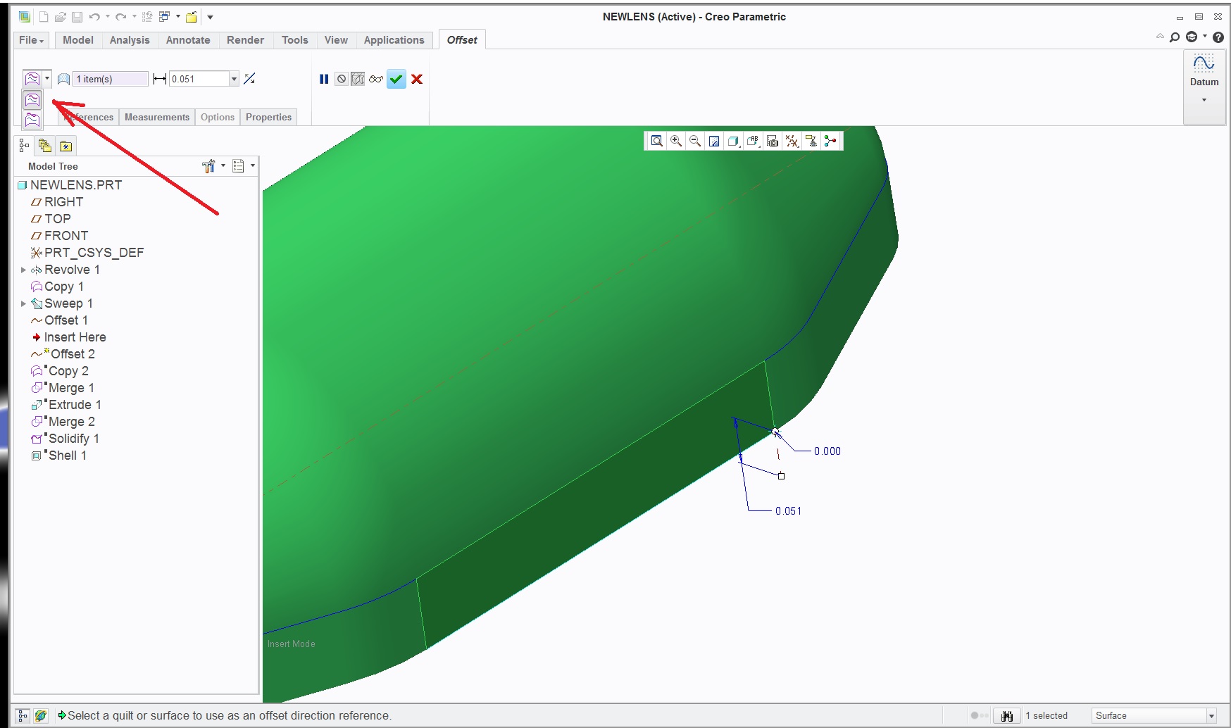
Richard,
It's a little convoluted...and dumb.
Set your filter (lower right on the screen) to Geometry.
Select the curve, click offset and set the value to 0.
Then select the "0" offset curve and click offset again. This time you will get the option to offset along or normal.
Sep 17, 2015
09:49 AM
- Mark as New
- Bookmark
- Subscribe
- Mute
- Subscribe to RSS Feed
- Permalink
- Notify Moderator
Please log in to access translation
Sep 17, 2015
09:49 AM
Richard,
While Dan's method works (as he said 'sometimes') knowing you are using these curves to build your glass rail, I suggest not using the approximate option. You will need to extend individual curves in order to trim them in tight corners. Approximate gets more involved especially if the curves are jittery to begin with.
Cheers
Sep 17, 2015
12:05 PM
- Mark as New
- Bookmark
- Subscribe
- Mute
- Subscribe to RSS Feed
- Permalink
- Notify Moderator
Please log in to access translation
Sep 17, 2015
12:05 PM
another method is sketch and project
when the imported geometry looks like this.
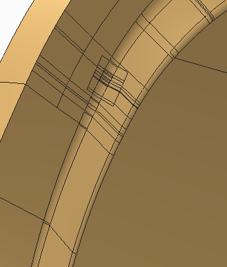
the first thing you do is have a good chuckle, looks a bit like my forehead where my hair used to be ;-)...
there are maybe a dozen surfaces on this model that can be copied_pasted and extended,
not a good thing when doing a mold split, curve copies are a bad joke here. this is the model that taught me to
"select the first curve in a chain copy and shift select additional curves in the curve window".
...but....even that way is no go, the geometry is junk.
when zoomed there are gaps that you could drive a vw bus towing a boat thru.
politics prevent us from fixing it.
in a sketch you can use edges, it can be dimension driven and tangent splines can be used to hop over the bad spots.
the clean sketch can be offset and then projected onto the surface/s, from there the surface can be trimmed and extended.
In this case you have to offset first to be sure the projected curve lies on the intended surface/s.
this is also an example where approximate can save the day.
Sep 24, 2015
10:54 AM
- Mark as New
- Bookmark
- Subscribe
- Mute
- Subscribe to RSS Feed
- Permalink
- Notify Moderator
Please log in to access translation
Sep 24, 2015
10:54 AM
Okay Folks,
Another question for all. How do I extend a surface along contour of the surface? In CATIA terms, it would be "extrapolate surface".
Regards


