
Turn on suggestions
Auto-suggest helps you quickly narrow down your search results by suggesting possible matches as you type.
Showing results for
Please log in to access translation
Turn on suggestions
Auto-suggest helps you quickly narrow down your search results by suggesting possible matches as you type.
Showing results for
Community Tip - Did you get an answer that solved your problem? Please mark it as an Accepted Solution so others with the same problem can find the answer easily. X
- Community
- Creo+ and Creo Parametric
- 3D Part & Assembly Design
- Re: An example of just how bad Pro/E sketcher can ...
Translate the entire conversation x
Please log in to access translation
Options
- Subscribe to RSS Feed
- Mark Topic as New
- Mark Topic as Read
- Float this Topic for Current User
- Bookmark
- Subscribe
- Mute
- Printer Friendly Page
An example of just how bad Pro/E sketcher can be
Mar 12, 2013
10:02 AM
- Mark as New
- Bookmark
- Subscribe
- Mute
- Subscribe to RSS Feed
- Permalink
- Notify Moderator
Please log in to access translation
Mar 12, 2013
10:02 AM
An example of just how bad Pro/E sketcher can be
Forget curvature and conics, this goes back to basics:
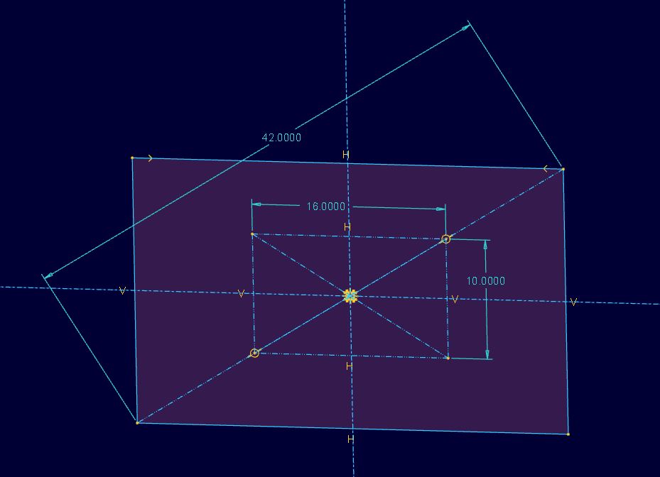
To compare two monitor screen sizes, I thought I'd quickly overlay two rectangles in Pro/E sketcher.
I drew one landscape rectangle, then another with a common point at the lower left.
I used Relations to say that the first rectangle should have a ratio of 16:10 and the second should have a ratio of 16:9
Then I added diagonals and tried to add lengths of 24" for the first and 27" for the second.
And that was when I remembered just how bad Pro/E is at handling constraints between entities: very bad. After unlocking the height dimension, you get an "overdefined" error anyway, despite there being only one driving dimension for each rectangle. Joy.
This thread is inactive and closed by the PTC Community Management Team. If you would like to provide a reply and re-open this thread, please notify the moderator and reference the thread. You may also use "Start a topic" button to ask a new question. Please be sure to include what version of the PTC product you are using so another community member knowledgeable about your version may be able to assist.
Labels:
- Labels:
-
2D Drawing
19 REPLIES 19
Mar 12, 2013
10:09 AM
- Mark as New
- Bookmark
- Subscribe
- Mute
- Subscribe to RSS Feed
- Permalink
- Notify Moderator
Please log in to access translation
Mar 12, 2013
10:09 AM
Unlocking a dimension means nothing to an overconstrained condition. What overconstrained means is that you have too many strong dimensions/constraints total, and that the sketcher does not need one of them to make the geometry work.
I wish it had a mode, for more complicated sketches, that made it such that you can turn off all constraints hen importing geometry. AND, what I'd like is for it to be more like AutoCAD, where you could truly turn off all assumed constraints, and manually pick them all.
Mar 12, 2013
10:33 AM
- Mark as New
- Bookmark
- Subscribe
- Mute
- Subscribe to RSS Feed
- Permalink
- Notify Moderator
Please log in to access translation
Mar 12, 2013
10:33 AM
Nonetheless, it remains a problem that you cannot define something as simple as a rectangle by ratio and diagonal length. It doesn't even work with Reference Dimensions. Other packages can do this, even SolidWorks. And of course it can, because there's nothing logically wrong with this type of definition.
I could give far more complex examples of when Pro/E Sketcher can't manage something that should be fine, but I thought this one demonstrated things nicely. Perhaps I'll post another example in the future if I can separate the sketch into a .sec file.
I'd like to be able to have a manual mode for constraints too. And AutoCAD's select method. But that's another topic.
Mar 12, 2013
10:32 AM
- Mark as New
- Bookmark
- Subscribe
- Mute
- Subscribe to RSS Feed
- Permalink
- Notify Moderator
Please log in to access translation
Mar 12, 2013
10:32 AM
This is a geometry restriction, not a pro/e restriction. As Frank indicated, a dimension that is not a reference dimension is driving the geometry, regardless if it's strong, weak or locked. You cannot control all three legs of a right triangle.
I'm not a big fan of sketcher relations as they are sort of buried constraints. You need to dig into not only the sketch but the relatsions dialog of the sketch to see what's going on.
In this case I'd use an angle to keep the proportions and the diagonal dimension to control the size. A 16:9 ratio would need an angle of 29.3574 degrees off the horizontal, for 16:10 it would be 32.0054 degrees off the horisontal.
Mar 12, 2013
10:35 AM
- Mark as New
- Bookmark
- Subscribe
- Mute
- Subscribe to RSS Feed
- Permalink
- Notify Moderator
Please log in to access translation
Mar 12, 2013
10:35 AM
No it isn't. If A = 2*B (where A is the horizontal and B is the vertical) then no size information has been added at all. A diagonal should be able to define the size. It is a Pro/E problem, not a logic paradox.
Mar 12, 2013
10:47 AM
- Mark as New
- Bookmark
- Subscribe
- Mute
- Subscribe to RSS Feed
- Permalink
- Notify Moderator
Please log in to access translation
Mar 12, 2013
10:47 AM
Sorry David, I have to disagree. If you have dimension A (width) and dimension B (height), then you have completely defined a rectangle and any other dimension is overconstrained, unless it's a reference dimension. In this scenario, while a relation may make A = 2*B, it doesn't factor into anything. You could comment it out and it wouldn't change anything. It is geometrically overconstrained, and you must either make the diagonal the reference dimension, or one of the other 2.
I'll have to disagree with Doug (just because I'm that retentive  ) and say that he's right....except about the weak dimension. A strong or locked dimension will make it overconstrained, a weak dimension will disappear as soon as the sketch is fully constrained.
Mar 12, 2013
11:02 AM
- Mark as New
- Bookmark
- Subscribe
- Mute
- Subscribe to RSS Feed
- Permalink
- Notify Moderator
Please log in to access translation
Mar 12, 2013
11:02 AM
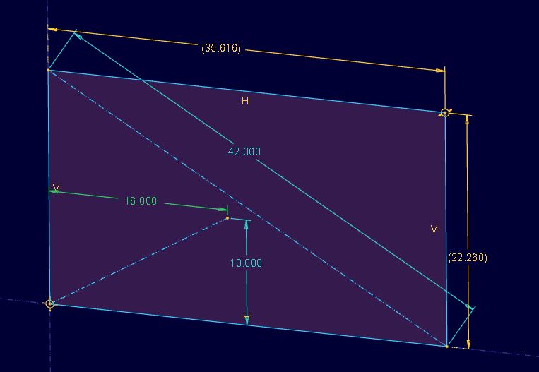
Yep, it will work using the relation
sd0 = rsd1 * 9/16
for the two perpendicular sides of the rectangle, where sd1 is changed to a reference dim (rsd1) before creating the relation. I can then update the (strong or locked) diagonal dimension sd2, and the whole rectangle follows.
However, it does seem a little flaky in regenerating every time (might require multiple regens before I'm certain that it's all updated, and doesn't handle large changes in the diagonal length) so I'd agree that the angle method is likely to be more robust.
I have to agree with Frank: this is a basic case of "necessary and sufficient" constraint. A rectangle is defined completely by two dimensions and a (set of) perpendicularity constraint(s); any more dimensions create overconstraint.
There's no difference between 'strong' and 'locked' for constraint purposes; 'locked' is mostly useful for controlling what is flexible when you drag a sketch (occasionally useful for significantly changing the shape without deleting everything and losing references).
Oh, and: AutoCAD has something better than Query Select? Where do I enable this?
Mar 12, 2013
11:44 AM
- Mark as New
- Bookmark
- Subscribe
- Mute
- Subscribe to RSS Feed
- Permalink
- Notify Moderator
Please log in to access translation
Mar 12, 2013
11:44 AM
I think we're splitting hairs, but Proe / Creo treats weak & strong dimensions the same as far as constraining the geometry. The only difference is the weak dims (theoretically) automatically go away if other dims or constraints are added that amke the sketch over constrained.
I found the same as Jonathan, if I create a ref dim for one side and drive the other dim from it with a relation, the sketch works. However because relations are not evaluated in real time the sketch does not update dynamically properly when the diagonal dim is changed. It takes exiting the sketch and maybe a regen to get it back to the proper proportion.
BTW - I just tried the same thing in SW 2012. I created the rectangle, added 16" H & 9" V dims and then added the point to point diagonal dim. SW said the sketch was over constrained and wanted me to make the diag driven. I left it overconstrained and went in and made the H driven to correct it. I then made an equation to drive the V dim by the H /16 * 9. No problem. I changed the diagonal to 24 but the V stayed at 9 until I exited the sketch. Only then did it take the proper proportion.
Just like Creo 2.
Mar 12, 2013
11:59 AM
- Mark as New
- Bookmark
- Subscribe
- Mute
- Subscribe to RSS Feed
- Permalink
- Notify Moderator
Please log in to access translation
Mar 12, 2013
11:59 AM
Let's just step back a minute. This isn't about rectangles. This is about the implications of not being able to define sd1 in terms of sd0 without assigning a value to sd0. A limitation which, in my experience, is unique to Pro/E.
The obvious workarounds which can be used to achieve the task given in this example (the rectangle) will not be practical in more complex scenarios.
As a side note, I'm not sure that anyone has grasped that you can define a rectangle by the ratio of the sides and the length of the diagonal. Understanding of that concept is fundamental to understanding this topic.
Mar 12, 2013
12:11 PM
- Mark as New
- Bookmark
- Subscribe
- Mute
- Subscribe to RSS Feed
- Permalink
- Notify Moderator
Please log in to access translation
Mar 12, 2013
12:11 PM
This is a computer program, and computers work with numbers. If you haven't assigned a value to sd0, how will you evaluate sd1?
Anyway, we've shown that you can define sd1 in terms of sd0 without sd0 being a 'driving' dimension, by making it a reference dimension. We just don't recommend it. A more robust approach, if you're wanting to use relations, might be to define your 'driving' dimension as a parameter and then define all other dimensions (in this case, height and width) directly from that. Or just remember to regenerate repeatedly...
I think the key problem you've identified is that Pro/E doesn't recognise a relation (which is really external to the sketch, whether it's at the feature or part level) as a constraint within the sketch - does other CAD software do this?
There is no sketcher constraint entity for "length = f(other length)" except for the special case where f(x) = x.
Mar 12, 2013
01:54 PM
- Mark as New
- Bookmark
- Subscribe
- Mute
- Subscribe to RSS Feed
- Permalink
- Notify Moderator
Please log in to access translation
Mar 12, 2013
01:54 PM
Well, David's relation could be at the SKETCHER level, and that should help a lot. wonder what he thinks of the solution I put in the .zip file below. I think that might be what he really wants.
Mar 12, 2013
02:18 PM
- Mark as New
- Bookmark
- Subscribe
- Mute
- Subscribe to RSS Feed
- Permalink
- Notify Moderator
Please log in to access translation
Mar 12, 2013
02:18 PM
When I tried it that's where I put it. Given the syntax of the relation he used above I assume he did as well.
It still doesn't update dynamically.
Mar 12, 2013
06:18 PM
- Mark as New
- Bookmark
- Subscribe
- Mute
- Subscribe to RSS Feed
- Permalink
- Notify Moderator
Please log in to access translation
Mar 12, 2013
06:18 PM
Try the model I posted at the bottom. I can drag the diagonal dimension dynamically and it all updates just fine with the ratio he wanted, or any other ratio.
Lemme know what ya think Doug.
Mar 12, 2013
12:29 PM
- Mark as New
- Bookmark
- Subscribe
- Mute
- Subscribe to RSS Feed
- Permalink
- Notify Moderator
Please log in to access translation
Mar 12, 2013
12:29 PM
Both Jonathon and I above defined the rectangle with a ratio between the H & W with a diagonal dim present. It requires that either the H or W be a reference dim and the other be defined via relation relative to it. It works, however, it will not update dynamically, the relations are only evaluated at regen or when exiting the sketch. And, I duplicated this behavior in SW 2012.
You want to do so with 3 driving dims and it's not possible. One needs to be a reference dim, or in SW terms a driven dim.
Yes, this is specific to this situation, however I'm not sure how to evaluate other theoretical situations. In this situation you're pushing against a geometry limit, perhaps in others it's software, I don't know.
Mar 12, 2013
12:44 PM
- Mark as New
- Bookmark
- Subscribe
- Mute
- Subscribe to RSS Feed
- Permalink
- Notify Moderator
Please log in to access translation
Mar 12, 2013
12:44 PM
Sometimes geometry is best for driving things in a sketcher, rather than relations. I think this is what you're after David. This model drives both X and Y values by the diagonal dimension, and the ration can easily be changed to 16:9 (or whatever).
Mar 12, 2013
08:36 PM
- Mark as New
- Bookmark
- Subscribe
- Mute
- Subscribe to RSS Feed
- Permalink
- Notify Moderator
Please log in to access translation
Mar 12, 2013
08:36 PM
This is so simple I don't even know why we are talking about it.
Mar 12, 2013
08:42 PM
- Mark as New
- Bookmark
- Subscribe
- Mute
- Subscribe to RSS Feed
- Permalink
- Notify Moderator
Please log in to access translation
Mar 12, 2013
08:42 PM
...and Frank made it even simpler:
Mar 13, 2013
08:45 AM
- Mark as New
- Bookmark
- Subscribe
- Mute
- Subscribe to RSS Feed
- Permalink
- Notify Moderator
Please log in to access translation
Mar 13, 2013
08:45 AM
Excellent! When I was playing with this I had a feeling that there was something I was missing that could make this much easier and intuitive.
Mar 13, 2013
09:54 AM
- Mark as New
- Bookmark
- Subscribe
- Mute
- Subscribe to RSS Feed
- Permalink
- Notify Moderator
Please log in to access translation
Mar 13, 2013
09:54 AM
That's me.....simple.
Mar 12, 2013
09:51 PM
- Mark as New
- Bookmark
- Subscribe
- Mute
- Subscribe to RSS Feed
- Permalink
- Notify Moderator
Please log in to access translation
Mar 12, 2013
09:51 PM
This is a sketch that governs the size of an icosahedron from any face to the center. It is perfectly "stable" which means that changing the one controlling value, 20 in this case, maintains the entire sketch without issue. Even the model that is driven by this is wholly dependent on this one dimension.
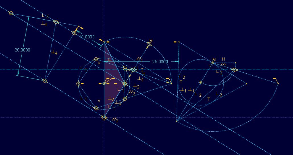
I could not even tell you exactly what each relation or reference diagram defines without study. The idea is that each "diagram" in this one section is independently developed and tied together with both geometry and relations. You don't just do this. You have to "understand" your subject before you can represent it in a sketch.
Point is, this is part of the "art" behind what PTC can do just as well if not better than other programs. As with anything else, you just have to learn how to make it work for you. What use would it be if a program can make an icosahedron but only define the sphere that contains it? All the extra geometry in this sketch is based on this single requirement. Changing it for different requirements is as simple as adding one dimension and referencing the current driving dimension.


