- Community
- Creo+ and Creo Parametric
- 3D Part & Assembly Design
- Re: AutoGEM will not mesh parts
- Subscribe to RSS Feed
- Mark Topic as New
- Mark Topic as Read
- Float this Topic for Current User
- Bookmark
- Subscribe
- Mute
- Printer Friendly Page
AutoGEM will not mesh parts
- Mark as New
- Bookmark
- Subscribe
- Mute
- Subscribe to RSS Feed
- Permalink
- Notify Moderator
AutoGEM will not mesh parts
I am using mechanica to analyze a set of brackets that mount to a transmission housing for support. I have everything setup in my analysis but I am having one hell of a time trying to get the transmission housing to mesh. In fact, I have been trying to get this thing to mesh for a solid week now.
Here is what I have done so far to try and get it working:
1. Turned off as many features (holes, rounds, etc) as possible to reduce the number of elements.
2. Carefully repaired all of the errors in the geometry (overlapping surfaces, etc.).
3. Ran AutoGEM successfully on each part individually (including the housing).
4. Tried suppressing one part at a time in my analysis to see if there was some sort of glitch with the analysis.
No matter what I try, AutoGEM will get 99% complete and stops without throwing any errors other than it is unable to mesh. The thing that really annoys me is that my counterparts in Japan have been able to run a similar FEA with the same transmission model and computer setup without issues.
Any ideas of things to try to get this working?
BTW, I am using 64bit Pro/E WF4.0.
This thread is inactive and closed by the PTC Community Management Team. If you would like to provide a reply and re-open this thread, please notify the moderator and reference the thread. You may also use "Start a topic" button to ask a new question. Please be sure to include what version of the PTC product you are using so another community member knowledgeable about your version may be able to assist.
- Labels:
-
General
- Mark as New
- Bookmark
- Subscribe
- Mute
- Subscribe to RSS Feed
- Permalink
- Notify Moderator
When you run the analysis on each part individually do you get any warnings in the diagnostic’s window?
If you do, this might lead you to the culprit. Also check your material properties for each part.
Hope this helps,
Don
- Mark as New
- Bookmark
- Subscribe
- Mute
- Subscribe to RSS Feed
- Permalink
- Notify Moderator
I succesfully meshed each part individually and did not receive any errors, only some warnings about edge angles. I also verified that all parts have a material property so I don't think that is it either.
Any other ideas?
- Mark as New
- Bookmark
- Subscribe
- Mute
- Subscribe to RSS Feed
- Permalink
- Notify Moderator
I have run into issues with surface warnings at the part level that would not let the assembly level analysis mesh.
Verify there are no surfaces created by rounds or blends that fold over it's self.
When you do a tolerance report in Simulate are they all close to each other in values?
Don
- Mark as New
- Bookmark
- Subscribe
- Mute
- Subscribe to RSS Feed
- Permalink
- Notify Moderator
I checked all the tolerances and they are good. I also started checking each part individually again and finally got it to throw an error. When I try to mesh one of the components of the main transmission case, I get the following error:
The highlighted surface(s) have C1 discontinuities.
Although Mechanica cannot create exact elements on these
surfaces, it has created approximate elements that may generate
invalid results.
The only problem is that it doesn't highlight anything.
- Mark as New
- Bookmark
- Subscribe
- Mute
- Subscribe to RSS Feed
- Permalink
- Notify Moderator
If you set the global interface definition to "free" does it mesh?
- Mark as New
- Bookmark
- Subscribe
- Mute
- Subscribe to RSS Feed
- Permalink
- Notify Moderator
If I understand you correctly, you are asking if I set the global definition to free rather than bonded does it mesh? If so, the answer is no...it still doesn't mesh.
- Mark as New
- Bookmark
- Subscribe
- Mute
- Subscribe to RSS Feed
- Permalink
- Notify Moderator
How is the accuracy defined for each part (you can check by going File -> Prepare -> Model Properties)? Relative or Absolute? This issue sounds like the mesher is having issues defining the geometry boundary with the appropriate level of tolerance.
Would it be possible for you to post your part and assembly files? How was the CAD geometry created? Did you use any free-form surfacing?
- Mark as New
- Bookmark
- Subscribe
- Mute
- Subscribe to RSS Feed
- Permalink
- Notify Moderator
The relative and absolute accuracy are set to the same value.
Sorry, I can't share the data because it is proprietary.
- Mark as New
- Bookmark
- Subscribe
- Mute
- Subscribe to RSS Feed
- Permalink
- Notify Moderator
Not sure exactly what you are asking. It is a casting model with all of the machining operations included, but I have turned off as many features as I can. The main issue is that most of the goemetry was copied as surfaces from other parts and the model is just "dirty".
- Mark as New
- Bookmark
- Subscribe
- Mute
- Subscribe to RSS Feed
- Permalink
- Notify Moderator
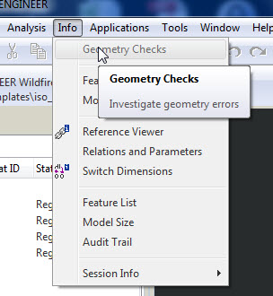
I don't have a Geometry Checks option in Wildfire 4.0. I have model check and it shows all kinds of errors, but somehow others in this company have meshed this exact same model with the exact same computer setup I'm using.
- Mark as New
- Bookmark
- Subscribe
- Mute
- Subscribe to RSS Feed
- Permalink
- Notify Moderator
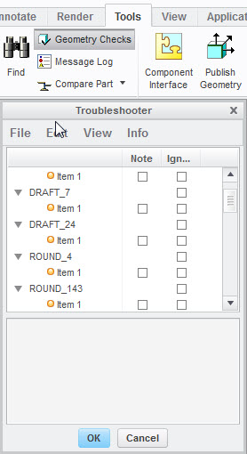
Steven's looking for the following info from the Geometry Checks command which is located under the Info tab in wildfire 4 and under the tools tab in Creo.


- Mark as New
- Bookmark
- Subscribe
- Mute
- Subscribe to RSS Feed
- Permalink
- Notify Moderator
It's there, but greyed out.
- Mark as New
- Bookmark
- Subscribe
- Mute
- Subscribe to RSS Feed
- Permalink
- Notify Moderator
Are you out of mechanica and in part only mode?
- Mark as New
- Bookmark
- Subscribe
- Mute
- Subscribe to RSS Feed
- Permalink
- Notify Moderator
Yes.
- Mark as New
- Bookmark
- Subscribe
- Mute
- Subscribe to RSS Feed
- Permalink
- Notify Moderator
I will when my company switches to it (our internal software only supports WF4 at the moment). At the rate we are going now, that should be some time in 2020.
- Mark as New
- Bookmark
- Subscribe
- Mute
- Subscribe to RSS Feed
- Permalink
- Notify Moderator
I have already verified the strength of my brackets, but now there is concern that I'm going to break the transmission.
- Mark as New
- Bookmark
- Subscribe
- Mute
- Subscribe to RSS Feed
- Permalink
- Notify Moderator
Hi,
Castings can be painful. Scanned data even worse. 'Model over the top' with simple protrusions is quickest (crudest) but effective way to get rid of dodgy rounds.
If brackets are sheetmetal, remodel as approximate normal parts.
Look out for tiny surfaces created where components touch and perimeters over/underlap. Adjust to map exactly.
Make sure there are no interferences. Fix if there are.
Confirm adjacent part accuracies are similar (use the tolerance report)
If there are any contacts with split surfaces switched on, either adjust components so they map exactly and/or switch off the split surfaces.
If the parts mesh but the assembly doesn't, suppress all components (and fasteners if any) and resume one part at a time until you find a potential culprit/area of the model. Freeze components if you have to in order to achieve a logical order to this.
Resume fasteners at the end (one at a time is necessary).
Other things I have tried in the past to narrow down the potential location of the problem include cutting away half or 3/4 of the casting, gradualy replace, 'machining back' and replacing with 'clean' protrusion where components meet.
- Mark as New
- Bookmark
- Subscribe
- Mute
- Subscribe to RSS Feed
- Permalink
- Notify Moderator
Not sure what did it, but after checking and trying several things here I got it to mesh!


