Community Tip - You can change your system assigned username to something more personal in your community settings. X
- Community
- Creo+ and Creo Parametric
- 3D Part & Assembly Design
- Re: Centre of Gravity (CG) for parts, assemblies a...
- Subscribe to RSS Feed
- Mark Topic as New
- Mark Topic as Read
- Float this Topic for Current User
- Bookmark
- Subscribe
- Mute
- Printer Friendly Page
Centre of Gravity (CG) for parts, assemblies and drawings to be shown as icon?
- Mark as New
- Bookmark
- Subscribe
- Mute
- Subscribe to RSS Feed
- Permalink
- Notify Moderator
Centre of Gravity (CG) for parts, assemblies and drawings to be shown as icon?
Hello,
How to generate Centre of Gravity (CG) for parts, assemblies and drawings; and that to be shown as icon.
Thanks
bhoopathy
Solved! Go to Solution.
Accepted Solutions
- Mark as New
- Bookmark
- Subscribe
- Mute
- Subscribe to RSS Feed
- Permalink
- Notify Moderator
To close this community thread on the ability to show Centre of Gravity (CG) for parts, assemblies and drawings as icon.
Summary of the proposed solutions:
Create a Datum Point or Coordinate System to represent the Center of Gravity in the 3D model:
- If you have the Behavioral Modeler (BMX) option or extension in your license:
- You can create an Analysis > Mass Properties feature and directly generate Datum Point and / or CSYS
See how to verify the modules included in your Creo license in article CS165589, and review Creo Design packages in CS298294
- If you do NOT have the BMX option:
- You can compute the Mass Properties from File > Prepare > Model Properties > Mass Properties > change to Generate Report, if they are not calculated automatically
- This should populate the PRO_MP_COGX, PRO_MP_COGY and PRO_MP_COGZ model parameters
- Create your own Datum Point or CSYS and constrain their dimensions with relations and the above parameters
- Refer article CS40552 for steps and details, and this PDF file posted in the thread
Use the created 3D Datum Point or CSYS to place the icon / symbol:
- Once the 3D reference is created you can use it to position your custom symbol (we can also imagine inserting a Sketch in 3D directly) or placing existing icon from the Palette, as suggested in article CS325823
- Tags:
- parameters
- Mark as New
- Bookmark
- Subscribe
- Mute
- Subscribe to RSS Feed
- Permalink
- Notify Moderator
As far as my understanding goes it is necessary to get the BMX extension in order to actually drop a point establishing center of gravity.
In the Mass Properties tab if you have BMX you can save a point. Otherwise you get the XYZ location but have to manually place a point.
I really think that it shouldn't be necessary to have an almost unrelated extension to place the center of gravity point.
I am hoping that someone else might be able to share an easier way.
- Mark as New
- Bookmark
- Subscribe
- Mute
- Subscribe to RSS Feed
- Permalink
- Notify Moderator
I think (having not tried it) you could do the following (I'm using Creo 2.0):
(1) Do the mass properties analysis.
(2) Save the analysis as a feature.
(3) Create a point with any X, Y, Z you like.
(4) Using relations, set the X, Y, Z coordinates of the point to the analysis results.
Admittedly, step (4) is the tricky part, because I don't know how you can access the values stored - is it CG_X, or CM_X, or what? But an advantage (?) of this method would presumably be that the the center of gravity point would move if you add any other features prior to the saved calculation feature.
- Mark as New
- Bookmark
- Subscribe
- Mute
- Subscribe to RSS Feed
- Permalink
- Notify Moderator
Ken you are correct with a slight modification
(1) Do the mass properties analysis.
(2) Save the analysis as a CYCS and point feature named COG
(3) Show these on the drawing
(4) Relate your symbol to the CYCS and or point and you are good
- Mark as New
- Bookmark
- Subscribe
- Mute
- Subscribe to RSS Feed
- Permalink
- Notify Moderator
Hi,
I tried your method and did a mass properties analysis on an assembly, and this assembly co-ordinate system is based on the vehicle IP, which is far away from the assembly.
So, when I did this, the COG (saved as feature) of the assembly resulted right at the center of the assembly.
I hope the result of COG, I have got is the correct one.
- Mark as New
- Bookmark
- Subscribe
- Mute
- Subscribe to RSS Feed
- Permalink
- Notify Moderator
Some time ago I created a guide on how to create a point on the Center of Gravity. As soon as you have the point you can show it in a drawing and put dimensions or an icon on it.
See PDF doc in the attachment.
- Mark as New
- Bookmark
- Subscribe
- Mute
- Subscribe to RSS Feed
- Permalink
- Notify Moderator
I like the idea behind your guide, but am wondering whether this might be more work than capturing individual X, Y and Z locations for placing a point?
This would work great however if you could capture this information in a start part or mapkey so you wouldn't have to work through all of the steps to create the offset point.
- Mark as New
- Bookmark
- Subscribe
- Mute
- Subscribe to RSS Feed
- Permalink
- Notify Moderator
You need to have the Advanced Assembly Extension or some form of the more advanced packages to do this easily. Having those you can create a feature at the end of your model tree which will store the CG. Once stored, in drawing mode you can add a symbol or create geometry in the drawing that is reference to the CG feature. You can lock it relative to the view and dimension it just like in your picture.
- Tags:
- aax
- Mark as New
- Bookmark
- Subscribe
- Mute
- Subscribe to RSS Feed
- Permalink
- Notify Moderator
ok,
I do what the guys said here but the trick will be the symbol, I tried this way first

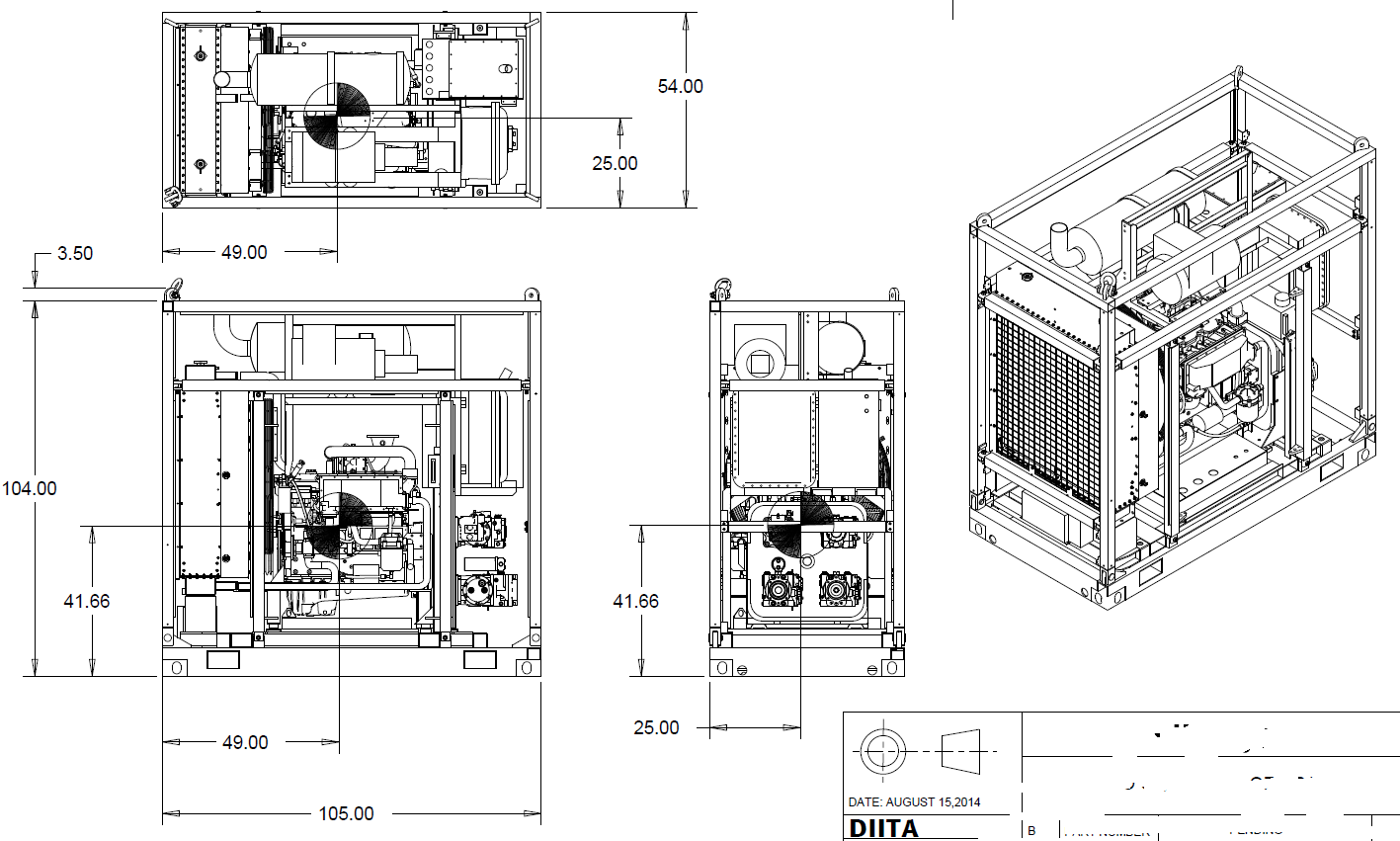
as you can see I draw the symbol on top of it, and I locate it close to what the mass properties window say,after all it is just a reference for loading purposes or tipping.
the down side of drawing this way that I have to spend sometime and if I move my views then it becomes a mess, an you can see the lines drawn.
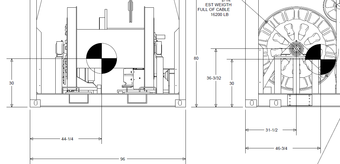
so the way I thought about making it quick and easy is if I do a cross section then I modify the hatch, and I can scale it easily so I just did a shaft with a 1/4 removed and i brought it to my drawing, created the cross section a place it on top of the CG point created based on the mass analysis, I guess it is easy enough

as you can see it looks solid and better than my fisrt try, I hope it helps
- Mark as New
- Bookmark
- Subscribe
- Mute
- Subscribe to RSS Feed
- Permalink
- Notify Moderator
Just a little extra information on this.
You can add to start part/assembly or in any model. I use CS0 or whatever your origin co-ordinate system is. Create a new CS from it. In the x y and z offsets use type pro_mp_cogx, pro_mp_cogy and pro_mp_cogz these will update when you recalculate mass properties and your cog position. Note there is also spin on this cog but I tend to ignore that most of the time. You can add point if you need to but should be able to locate a symbol on the CS.
- Mark as New
- Bookmark
- Subscribe
- Mute
- Subscribe to RSS Feed
- Permalink
- Notify Moderator
To close this community thread on the ability to show Centre of Gravity (CG) for parts, assemblies and drawings as icon.
Summary of the proposed solutions:
Create a Datum Point or Coordinate System to represent the Center of Gravity in the 3D model:
- If you have the Behavioral Modeler (BMX) option or extension in your license:
- You can create an Analysis > Mass Properties feature and directly generate Datum Point and / or CSYS
See how to verify the modules included in your Creo license in article CS165589, and review Creo Design packages in CS298294
- If you do NOT have the BMX option:
- You can compute the Mass Properties from File > Prepare > Model Properties > Mass Properties > change to Generate Report, if they are not calculated automatically
- This should populate the PRO_MP_COGX, PRO_MP_COGY and PRO_MP_COGZ model parameters
- Create your own Datum Point or CSYS and constrain their dimensions with relations and the above parameters
- Refer article CS40552 for steps and details, and this PDF file posted in the thread
Use the created 3D Datum Point or CSYS to place the icon / symbol:
- Once the 3D reference is created you can use it to position your custom symbol (we can also imagine inserting a Sketch in 3D directly) or placing existing icon from the Palette, as suggested in article CS325823
- Tags:
- parameters


