Community Tip - Want the oppurtunity to discuss enhancements to PTC products? Join a working group! X
- Community
- Creo+ and Creo Parametric
- 3D Part & Assembly Design
- Re: Constraining a countersunk screw into a counte...
- Subscribe to RSS Feed
- Mark Topic as New
- Mark Topic as Read
- Float this Topic for Current User
- Bookmark
- Subscribe
- Mute
- Printer Friendly Page
Constraining a countersunk screw into a countersunk hole?
- Mark as New
- Bookmark
- Subscribe
- Mute
- Subscribe to RSS Feed
- Permalink
- Notify Moderator
Constraining a countersunk screw into a countersunk hole?
I have not been formally taught how to use PTC software so have learnt everything by intuition, playing, a few guides and the help of you on here.
However having said all of that, I am somewhat confused on the method of correctly assembling a counter sunk screw into a countersunk hole. What makes sense to me is to:
1) Make the cylindrical part of the screw centered on the cylindrical part of the hole, or use axis alignment if there is no cylindrical part (material too thin)
2) Make the conical surface of the hole coincident with the conical surface of the screw.
Now to me there is nowhere else that screw can be than fuly mated in the hole. However Creo is saying that the screw is only partially constrained, how can that be?
Help! ![]()
This thread is inactive and closed by the PTC Community Management Team. If you would like to provide a reply and re-open this thread, please notify the moderator and reference the thread. You may also use "Start a topic" button to ask a new question. Please be sure to include what version of the PTC product you are using so another community member knowledgeable about your version may be able to assist.
Solved! Go to Solution.
Accepted Solutions
- Mark as New
- Bookmark
- Subscribe
- Mute
- Subscribe to RSS Feed
- Permalink
- Notify Moderator
I've done it!!!! ![]()
Constraint1 = COINCIDENT conical surface of screw head to conical surface of hole.
Constraint2 = TANGENT conical surface of screw head to conical surface of hole.
Screw is not fully constrained (it can be dragged out of the hole or rotated) but by default appears in the right place and will move up and down depending on the geometry of the hole.
No need to create extra datums.
- Mark as New
- Bookmark
- Subscribe
- Mute
- Subscribe to RSS Feed
- Permalink
- Notify Moderator
Can it still spin in the hole? In Wildfire (I haven't yet upgraded), if you check 'allow assumptions' it should show as fully constrained. Alternatively, you could also orient a datum through the axis to one of your assembly datums...
- Mark as New
- Bookmark
- Subscribe
- Mute
- Subscribe to RSS Feed
- Permalink
- Notify Moderator
The is no allow assumptions in Creo like there is in WF.
- Mark as New
- Bookmark
- Subscribe
- Mute
- Subscribe to RSS Feed
- Permalink
- Notify Moderator
Hi Colin
There is still allow assumption in CREO
Check the image below
- Mark as New
- Bookmark
- Subscribe
- Mute
- Subscribe to RSS Feed
- Permalink
- Notify Moderator
Allow assumptions does not appear until I have added the third (counter productive) constraint of flat surface on top of screw to flat surface of panel. The assumption I assume is to do with the rotation about the axis which I don't care about.
- Mark as New
- Bookmark
- Subscribe
- Mute
- Subscribe to RSS Feed
- Permalink
- Notify Moderator
I can't say for sure in Creo since I'm not using it but Wilfire 5 what I've noticed is when you select the conical surfaces it creates an insert constraint. However, it appears that what it does is aligns the axes and because of this you can flip the direction of the constraint and the part will flip its direction which is the reason it is only partially constrained. You have essentially created the same constraint. You will need to select the mate constraint from the list first and then select the conical surfaces. I believe it's possible to constrain a countersunk screw with a single mate constraint with the allow assumptions checked.
- Mark as New
- Bookmark
- Subscribe
- Mute
- Subscribe to RSS Feed
- Permalink
- Notify Moderator
Hi Colin
if you are working in CREO then you should check for remaining degees of freedom while assembling.(check the image below)
1.Whether you select cylindrical part to cylindrical part or conical part to conical part ;CREO will consider it to be a co-axial constrain. Even after these 2 constrains you will see one degree of freedom(because it will not consider conical surfaces as mate or aline constrain)
2. you must give another constrain to limit the remaining degree of freedom(a distance constrain(mate and aline constrain in wf) between the top flat surface of the conical part and the flat surface of the counter part will do)
Regards
K.Mahanta
- Mark as New
- Bookmark
- Subscribe
- Mute
- Subscribe to RSS Feed
- Permalink
- Notify Moderator
I think I understand what you are saying but my problem still is that I can't dimensionally constrain the top surface of the screw to the top surface of the sheet metal part containing the countersunk hole because that is the dimension I am trying to establish.
When the head of the screw sits in the countersunk hole I need the geometry to establish if it is proud, flush or sub-flush to the surface of the sheet metal part when the conical part of the screw head is sitting tight against the connical part of the hole. If the size of the counter sunk hole in the sheet metal part is changed then the screw head needs to automatically move up and down relative the the top surface.
I think I need a bit more play time. ![]()
- Mark as New
- Bookmark
- Subscribe
- Mute
- Subscribe to RSS Feed
- Permalink
- Notify Moderator
Colin,
A distance constraint that Kshetrebasi is speaking of can be a coincedent constraint between the top surface of the part and the top surface of the countersunk screw.
What Jonathon says below is correct: you'll want to do either an axis constraint or an insert constraint first.
- Mark as New
- Bookmark
- Subscribe
- Mute
- Subscribe to RSS Feed
- Permalink
- Notify Moderator
That is the problem. If I make a coincident constraint betwwwn the top of the screw and the top surface of the plate then how can I ever have a sub-flush screw?
If the counter sink is made deeper the screw just stays in the same place and the two conical surface just move further apart.
If the countersink is too shallow then the conical part of the screw head will cause an interference with the sheet, rather than "push" the screw head proud of the sheet surface.
The insert contraint has dissapeared in Creo which is why as stated in my original post I was doing coincident on the axis of the screw and hole incase there was no cylindrical part of the hole due to the panel being too thin.
- Mark as New
- Bookmark
- Subscribe
- Mute
- Subscribe to RSS Feed
- Permalink
- Notify Moderator
Ok - how about this.
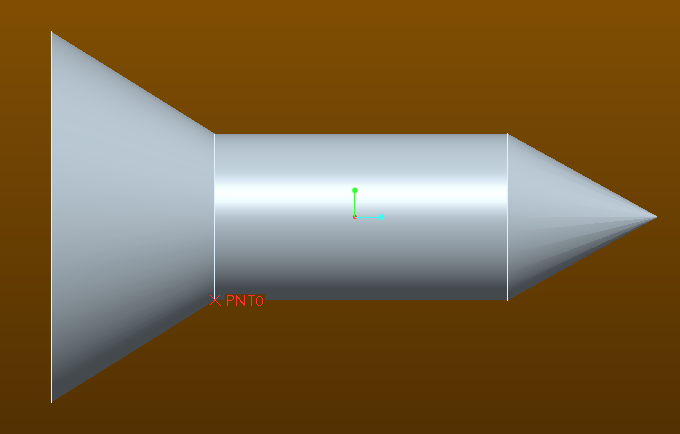
Make a point at the bottom of the "V" countersink on both the screw and the hole. Mate with those points.
I think this will allow what you are looking for because if the hole changes, the screw will not and it will stay fixed at the bottom of the "V". If the CS hole changes, the depth of the CS usually does, too.
- Mark as New
- Bookmark
- Subscribe
- Mute
- Subscribe to RSS Feed
- Permalink
- Notify Moderator
I've done it!!!! ![]()
Constraint1 = COINCIDENT conical surface of screw head to conical surface of hole.
Constraint2 = TANGENT conical surface of screw head to conical surface of hole.
Screw is not fully constrained (it can be dragged out of the hole or rotated) but by default appears in the right place and will move up and down depending on the geometry of the hole.
No need to create extra datums.
- Mark as New
- Bookmark
- Subscribe
- Mute
- Subscribe to RSS Feed
- Permalink
- Notify Moderator
Doesn't a mate constraint do what your looking for? If not what am I missing in what you are trying to do?
- Mark as New
- Bookmark
- Subscribe
- Mute
- Subscribe to RSS Feed
- Permalink
- Notify Moderator
You are thinking of pre-Creo constraints.
Yes, in Pro/E Wildfire, mating conical surfaces works perfectly. Because it was perfect, PTC decided to change it and make it worse, because that's what they do.
- Mark as New
- Bookmark
- Subscribe
- Mute
- Subscribe to RSS Feed
- Permalink
- Notify Moderator
In order to fully constrain it, you can create a geometry point on both the diameter edge of the screw and diameter edge of the hole, and constrain those two points.
- Mark as New
- Bookmark
- Subscribe
- Mute
- Subscribe to RSS Feed
- Permalink
- Notify Moderator
I've used Point On Surface to constrain awkward, conical geometry before. It's usually more reliable to specify the type of constraint before selecting references; then find a vertex at the minor diameter of the hole countersink, and use the conical surface of the fastener head.
You'd want an axis or cylindrical Insert as the first constraint.
- Mark as New
- Bookmark
- Subscribe
- Mute
- Subscribe to RSS Feed
- Permalink
- Notify Moderator
countersunk screw:
Create Datum Axis (A_2): Through the two vertices on the edge of the countersunk
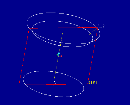
assembly component
a. Align: countersunk screw: A_1 + countersunk hole: hole axis
b. Pnt On Line: countersunk screw: A_2 + countersunk hole: Vertex in the chamfer edge
- Mark as New
- Bookmark
- Subscribe
- Mute
- Subscribe to RSS Feed
- Permalink
- Notify Moderator
If I remember correctly, you can simply use that ertice or line and constrain "point on surface" or "line on surface" without having to create an axis.
- Mark as New
- Bookmark
- Subscribe
- Mute
- Subscribe to RSS Feed
- Permalink
- Notify Moderator
"point on surface" Did not calculate the surface extension.
Pay attention to the regeneration.
- Mark as New
- Bookmark
- Subscribe
- Mute
- Subscribe to RSS Feed
- Permalink
- Notify Moderator
Colin,
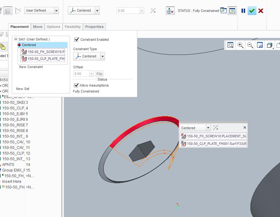
Does the "centered" constraint give you what you are looking for. I tested it quickly and it seems to regenerate as you are wanting, and it only took the one constraint to place it with the references being the conical surface of the screw, and the conical surface of the countersink.
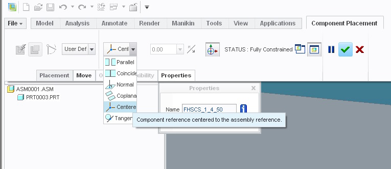
-Greg
- Mark as New
- Bookmark
- Subscribe
- Mute
- Subscribe to RSS Feed
- Permalink
- Notify Moderator
Greg, Centered on it's own doesn't mate the screw correctly for me, but I have now found the solution which works for me.
- Mark as New
- Bookmark
- Subscribe
- Mute
- Subscribe to RSS Feed
- Permalink
- Notify Moderator
If it could help other users, as Kevin said, a "Mate" constraint works.
I make it this way since Wildfire 3 (I'm now using WF5).
You just have to select "Mate" constraint type first, then select the two conical surfaces (screw+hole).
Obviously, "Allow assumptions" have to be checked.
- Mark as New
- Bookmark
- Subscribe
- Mute
- Subscribe to RSS Feed
- Permalink
- Notify Moderator
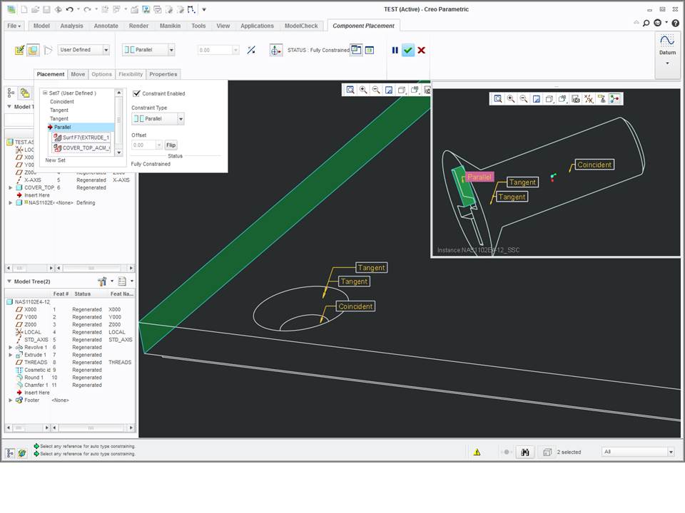
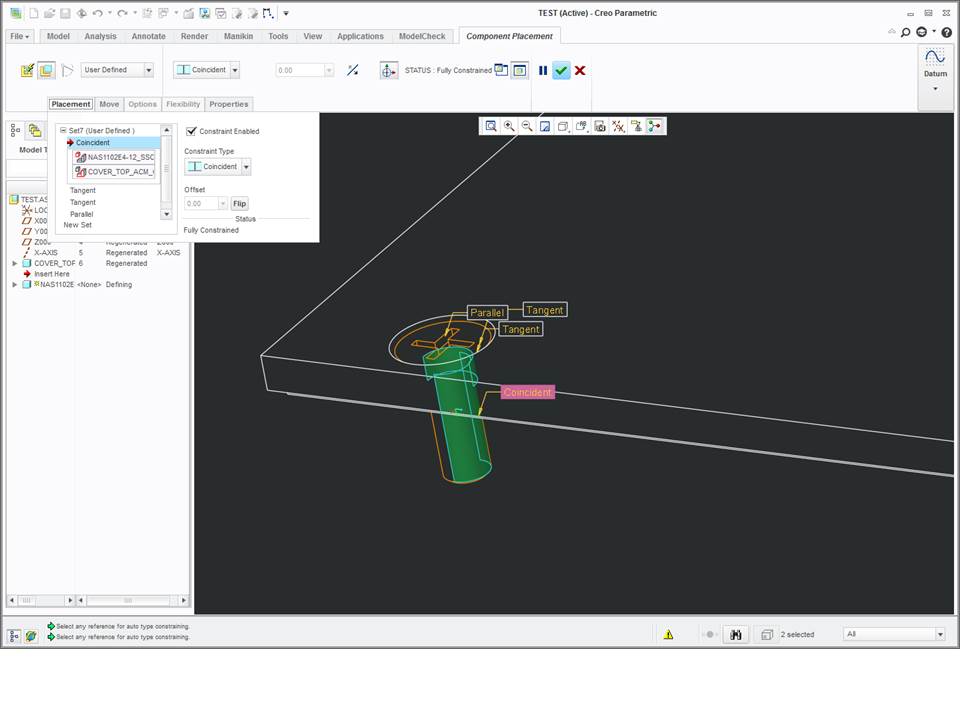
I'm working in CREO 2.0 where mate is no longer an option, and coincident doesn't fully constrain the assembly. In WF 5, one could constrain a countersunk screw to a countersunk hole by aligning the cylinder with hole then mate the two countersink surfaces. CREO 2.0 doesn't work the same...no mate.
This doesn't make complete sense to me, but it works and fully constrains the assembly.
coincident cylinders
tangent countersink surfaces
tangent countersink surfaces...again
parallel drive surface...for clocking
- Mark as New
- Bookmark
- Subscribe
- Mute
- Subscribe to RSS Feed
- Permalink
- Notify Moderator
After numerous attempts I have figured out a way that works for flat head (countersunk) screws in Creo 3.
1. Select the surface on the screw conical, select the vertex of the receiving hole:
2. Select the 2 axis and make them coincident:
3. A third and final constraint is required. You can use a Datum of the Screw and a Datum of the Assembly for Parallelism or you can use the constraint “Angular Offset”:
4. Verify tangency using “Pairs Clearance”:
- Mark as New
- Bookmark
- Subscribe
- Mute
- Subscribe to RSS Feed
- Permalink
- Notify Moderator
In Creo 2 you can just use "Centered" provided that the angle of the screw conical surface and the hole conical surface are identical.
- Mark as New
- Bookmark
- Subscribe
- Mute
- Subscribe to RSS Feed
- Permalink
- Notify Moderator
Yep this is exactly what I was writing on the 26th february ! ![]()
- Mark as New
- Bookmark
- Subscribe
- Mute
- Subscribe to RSS Feed
- Permalink
- Notify Moderator
Hello,
I often use this type of screws since many years, coincident on the cylinder part and centered on the conical part works perfectly.


