
Turn on suggestions
Auto-suggest helps you quickly narrow down your search results by suggesting possible matches as you type.
Showing results for
Please log in to access translation
Turn on suggestions
Auto-suggest helps you quickly narrow down your search results by suggesting possible matches as you type.
Showing results for
Community Tip - You can change your system assigned username to something more personal in your community settings. X
- Community
- Creo+ and Creo Parametric
- 3D Part & Assembly Design
- Curve from equation with part parameters
Translate the entire conversation x
Please log in to access translation
Options
- Subscribe to RSS Feed
- Mark Topic as New
- Mark Topic as Read
- Float this Topic for Current User
- Bookmark
- Subscribe
- Mute
- Printer Friendly Page
Curve from equation with part parameters
Jan 30, 2020
04:23 AM
- Mark as New
- Bookmark
- Subscribe
- Mute
- Subscribe to RSS Feed
- Permalink
- Notify Moderator
Please log in to access translation
Jan 30, 2020
04:23 AM
Curve from equation with part parameters
I'm trying to create a generic model for involute gears that are driven by parameters and relations. I'm also trying to use the part parameters (module, number of teeth, pressure angle) for the involute curve generation, but I noticed that the parameters for equations differ from part parameters (different option from the drop down menu in the parameters window).
Does anyone another way to connect the curve with the part parameters?
Labels:
- Labels:
-
General
10 REPLIES 10
Jan 30, 2020
06:03 AM
- Mark as New
- Bookmark
- Subscribe
- Mute
- Subscribe to RSS Feed
- Permalink
- Notify Moderator
Please log in to access translation
Jan 30, 2020
06:03 AM
Just type part parameter names to equation?
Say you have part level parameter called DIAMETER (Real Number), then one can create curve from equation; Cylindrical.
r =diameter/2
theta = t * 360
z = 0
- Tags:
- ust t
Jan 30, 2020
09:37 AM
- Mark as New
- Bookmark
- Subscribe
- Mute
- Subscribe to RSS Feed
- Permalink
- Notify Moderator
Please log in to access translation
Jan 30, 2020
09:37 AM
My mistake was naming the number of teeth Z (german influence), which also happens to be a coordinate axis/direction. Idiot me....
Thanks for the answer!
Jan 30, 2020
07:19 AM
- Mark as New
- Bookmark
- Subscribe
- Mute
- Subscribe to RSS Feed
- Permalink
- Notify Moderator
Please log in to access translation
Jan 30, 2020
07:19 AM
I've built a few gears with involute curves and what Mikko suggests is exactly what I did. You define your parameters, then use them to define the parametric equations defining the three spacial coordinates for your curve. I don't think I was able to look at the part parameters as I defined the curve driven equation. I had to bounce out of the curve definition, make sure of what my desired parameter was, then plug that into the equations.
I found that the equations are much simpler if I use r, theta and z rather than x, y, and z. The curve definition from one of my parts is:
r     = diabase * sqrt ( 1.0 + ( PI * t / 180.0 )^2 ) / 2.0
theta = t - atan ( PI * t / 180.0 )
z     = 0.0
Also, a big tip. I found that I had to define a half tooth, then mirror it, then pattern it around the axis of the gear. My initial attempt at this was to use the involute curve as a reference of a full tooth sketch. One side of the tooth was a direct "use curve" that used the equation driven curve. The other side was a mirror of the first about the center of the tooth. This seemed to work, looked okay, etc. But, what I found later was that if I had to change the definition (i.e. I wanted 42 teeth instead of 44) the teeth were no longer perfectly symmetric. The mirrored side would vary, particularly in curvature, from the side driven directly by the equations. My theory is this is because Creo is using a spline for the mirrored side that is an approximation. When I change dimensions, it's not like the program is "re-mirroring" the equation driven curve, but somehow adjusting that approximation to suit the situation. In other words, there doesn't seem to be a mathematical "link" between the mirrored curve and the driven one. Thus, I found that mirroring a half tooth was the only way I could have perfectly symmetric teeth in my gear.
Another thing I learned along the way is to define all the driving dimensions of the gear using parameters. Name them with easy to understand names, like numTeeth, etc. Thus, when I wanted to make another gear (and another, etc.) it was much easier to go into the parameters and change all the pertinent values rather than editing all the features.
Jan 30, 2020
09:40 AM
- Mark as New
- Bookmark
- Subscribe
- Mute
- Subscribe to RSS Feed
- Permalink
- Notify Moderator
Please log in to access translation
Jan 30, 2020
09:40 AM
Please rember to use Exact relations for values that define number of theeths.
These are diffrent:
Angle = 360/7
Angle = (360/7)
Later is suggested.
These are diffrent:
Angle = 360/7
Angle = (360/7)
Later is suggested.
Jan 30, 2020
09:41 AM
- Mark as New
- Bookmark
- Subscribe
- Mute
- Subscribe to RSS Feed
- Permalink
- Notify Moderator
Please log in to access translation
Jan 30, 2020
09:41 AM
What is the difference?
Jan 30, 2020
10:00 AM
- Mark as New
- Bookmark
- Subscribe
- Mute
- Subscribe to RSS Feed
- Permalink
- Notify Moderator
Please log in to access translation
Jan 30, 2020
10:00 AM
Cant find documentation, but the idea is, that 1/7 is handeled as real number, with limited number of digits, while (1/7) is kept as pricise fraction.
This was at some years bck presented in "whats new" material.
This was at some years bck presented in "whats new" material.
Jan 30, 2020
11:09 AM
- Mark as New
- Bookmark
- Subscribe
- Mute
- Subscribe to RSS Feed
- Permalink
- Notify Moderator
Please log in to access translation
Jan 30, 2020
11:09 AM
Interesting, thanks for the info!
Jan 30, 2020
11:08 AM
- Mark as New
- Bookmark
- Subscribe
- Mute
- Subscribe to RSS Feed
- Permalink
- Notify Moderator
Please log in to access translation
Jan 30, 2020
11:08 AM
See my response to Mikko's answer.
How did you create the tooth without converting the equation driven curve into a spline?
Also: the polar coordinate curve equation you posted bellow returns a failed feature even, I could not figure out why.
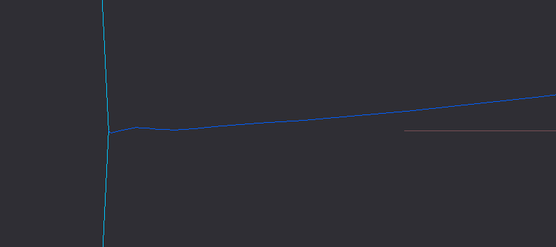
Edit: I attached a screenshot of a zoomed-in start of the curve next to the base circle. Is this wiggle shape common?
Jan 30, 2020
02:49 PM
- Mark as New
- Bookmark
- Subscribe
- Mute
- Subscribe to RSS Feed
- Permalink
- Notify Moderator
Please log in to access translation
Jan 30, 2020
02:49 PM
Few notes & config.pro options are written in Italics:
Accuracy
- File>Prepare>Model Properties>Accuracy
- You should run this on absolute accuracy
- enable_absolute_accuracy yes
- default_abs_accuracy ###
- accuracy_lower_bound ###, if required
Display config.pro options
- shade_with curves
- edge_display_quality very_high
- enable_fsaa 16
- smooth_lines yes
- skip_small_surfaces no
***
The equation at this thread for cylindrical csys works OK with Creo Parametric 6.0.3.0.
It will be XY plane. The length of curve is depended on variable t. For BASEDIA=10, I used 0<t<50 to get visualization.
See image attached.
***
One can start the modelling of gear by declaring initial variables in part level relation:
DIABASE=10
MODULUS=4
.... etc
Then create curve by equation and copy paste those part level relations in curve by equation dialog. Comment all rows with /* Now you have all variables at your fingertips.
When curve definition is ready you can delete part level relations (and all commented curve by equation level rows).
The parameters are still in model and can be used to drive model. Remember that you can also use name of dimension instead of name of parameter in relations.
***
Cant really confirm the 1/7, (1/7) thing. Cant find any documentation on it, nor reproduce any sample.
Jan 30, 2020
03:14 PM
- Mark as New
- Bookmark
- Subscribe
- Mute
- Subscribe to RSS Feed
- Permalink
- Notify Moderator
Please log in to access translation
Jan 30, 2020
03:14 PM
The equations I gave are what I use in the model I've created. Since it's the only parameter in there, I'd guess that maybe the "diaBase" is the problem. For me that's a parameter calculated for the specific tooling we're defining. The gears I'm making are not strictly gears for mechanisms, they are rolling forming gears. diaBase is not diaPitch, but is calculated with the pitch diameter
diaBase = diaPitch * COS ( 90.0 - angCell )These parameters and such are specific to our gears. If you're trying to define an involute gear there are lots of discussions in this forum and in the past talking about how to do so. It's something that comes up on a regular basis, same as "how do I define a realistic spring with closed ends?".
As for how to make the tooth:
(1) I build the involute curve. If my math is correct, it lies exactly where the side of the tooth needs to be.
(2) I build a protrusion feature. The section for the tooth uses a projection of the equation driven curve, an arc at the outer diameter of the gear, an arc at the base of the tooth, a line at the mid plane of the tooth, and a line at an angle of 360 / (numTeeth * 2 ) from the center of the tooth.
(3) Mirror that half tooth to make a full tooth.
(4) Pattern that tooth with numTeeth instances, angular pitch of 360 / numTeeth.
There are a bunch of calculations that I do prior to this stuff, too. But they're pretty much relevant to our particular tools, and not for someone trying to make a standard gear. Looking about in the previous discussions and getting an understanding of the underlying mathematics will make things clear, I hope.


