Community Tip - Need to share some code when posting a question or reply? Make sure to use the "Insert code sample" menu option. Learn more! X
- Community
- Creo+ and Creo Parametric
- 3D Part & Assembly Design
- Re: Drawings unstable in Creo 2.0?
- Subscribe to RSS Feed
- Mark Topic as New
- Mark Topic as Read
- Float this Topic for Current User
- Bookmark
- Subscribe
- Mute
- Printer Friendly Page
Drawings unstable in Creo 2.0?
- Mark as New
- Bookmark
- Subscribe
- Mute
- Subscribe to RSS Feed
- Permalink
- Notify Moderator
Drawings unstable in Creo 2.0?
I just completed a very comprehensive machining drawing and I must say that between 2000i and Creo 2.0, the drawing had become seriously unstable.
1st I was dealing with some very annoying graphics artifacts. Ones where simply moving an annotation feature would blank out the feature. More often than not, I would have to regenerate the drawing to get things to unhighlight or come back to a visible state. Seriously annoying indeed!
Then I had whole blocks of dimensions and other features just -move-. They jumbled themselves up left and right generally undoing a lot of careful placement that I was -doing-. It happened sometime between switching to the model and drawing, and poof, I again had to fix a couple of dozen annotation features.
Am I the only one? ...or is this something that has become the norm? Seriously, in 2000i, it was set it and forget it. Now I don't know how people keep from pulling their hair out.
I am on an approved platform with the approved drivers... etc.
This thread is inactive and closed by the PTC Community Management Team. If you would like to provide a reply and re-open this thread, please notify the moderator and reference the thread. You may also use "Start a topic" button to ask a new question. Please be sure to include what version of the PTC product you are using so another community member knowledgeable about your version may be able to assist.
- Labels:
-
General
- Mark as New
- Bookmark
- Subscribe
- Mute
- Subscribe to RSS Feed
- Permalink
- Notify Moderator
Us old guys still have a few tricks up our sleeves..... ![]()
If you guys like, I have a couple cool symbols I can e-mail ya.
- Mark as New
- Bookmark
- Subscribe
- Mute
- Subscribe to RSS Feed
- Permalink
- Notify Moderator
Sorry, ... I did download your zip and rebuilt it as an excersize. I shortened the leader to 3/8" which is default. Strange that the symbol interface didn't have the "fill" or "X-hatch" region funtion.
I can see the need for this ability in the future. Worth looking at it while I have a need at hand. I'd never used symbols (nor needed them) in the past.
- Mark as New
- Bookmark
- Subscribe
- Mute
- Subscribe to RSS Feed
- Permalink
- Notify Moderator
If the symbols were old enough, perhaps the fill/hatch option is automatically disabled. That was only added very recently. I complained about that one for years! I'm glad it's finally fixed for new symbols. Maybe, for some reason, it doesn't appear for symbols created before WF5 (when the hatch/fill was added if I remember correctly).
- Mark as New
- Bookmark
- Subscribe
- Mute
- Subscribe to RSS Feed
- Permalink
- Notify Moderator
I created the symbol in WF4. I didn't think about "fill", since Pro/E's 2d capability is subpar. I actually created the geometry as a curve in modeling mode to easily get the proportions right, then made a quick dwg, and copied the geometry in a dwg to actually make the symbol.
Now, you could probably get tricky and make a bunch of parameters in the dwg for datum A etc., and use those parameters in the symbol so all the symbols would change if the datum changed, but, to me that seemed too much bother. You could also probably also use a parameter of the datum feature.....
- Mark as New
- Bookmark
- Subscribe
- Mute
- Subscribe to RSS Feed
- Permalink
- Notify Moderator
Funny thing... since I use the iso30985font for this client, the datum tag generated by PTC is too narrow. the box is not square by almost 10%.
- Mark as New
- Bookmark
- Subscribe
- Mute
- Subscribe to RSS Feed
- Permalink
- Notify Moderator
I did my symbol from scratch, Brian... I didn't see Fill as a command anywhere.
Care to point it out?
- Mark as New
- Bookmark
- Subscribe
- Mute
- Subscribe to RSS Feed
- Permalink
- Notify Moderator
Can't say for sure since I haven't looked at it but I think how the fill is created is by the hatch on the sketch tab (I think that's where it's located). One of the option for hatch should be fill.
- Mark as New
- Bookmark
- Subscribe
- Mute
- Subscribe to RSS Feed
- Permalink
- Notify Moderator
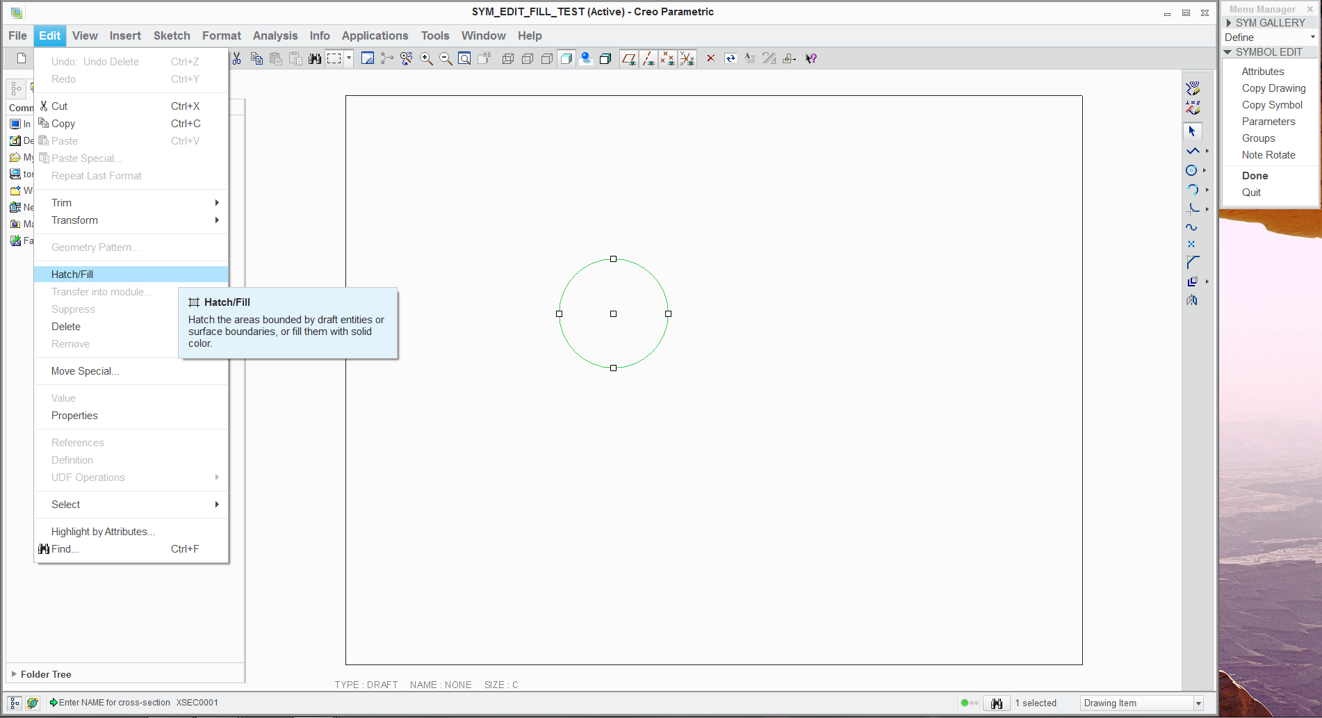
Glad I asked. It is under EDIT.
Here's a screenshot of the Creo 2.0 symbol "sketcher". Looks a lot like WF huh ![]()

- Mark as New
- Bookmark
- Subscribe
- Mute
- Subscribe to RSS Feed
- Permalink
- Notify Moderator
Oh this is sad!


This is going to drive me absolutely mad! Just kill me now, please.
So I edit the datum symbol to use the fill and as I test it, it blows up. Should have known! ![]()
I attached the symbol to see if anyone else gets what I got.
Since we opened Pandora's Box with the thought of using "fills", it might be good to be forewarned about what may happen.
BTW: it does plot properly so it is simply a graphics artifact. In my case, Dell w/ N-Vidia Quadro 3000
Glad I kept the original version with the lines to create the fill.
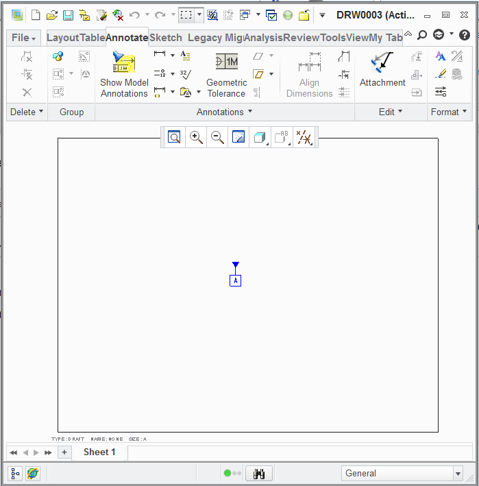
Image 1... correct results
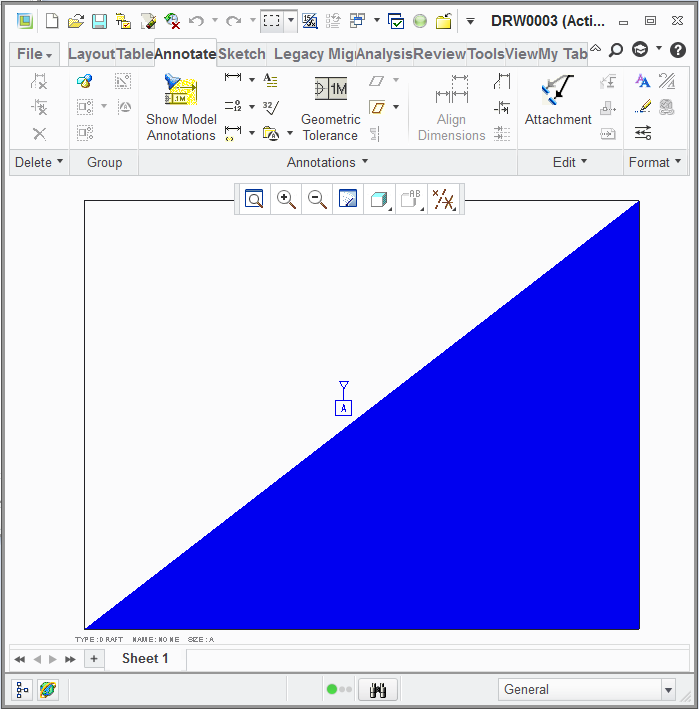
image 2... serious graphics corruption
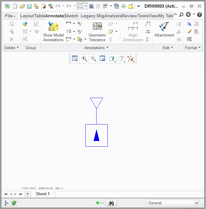
image 3... confused fill


- Mark as New
- Bookmark
- Subscribe
- Mute
- Subscribe to RSS Feed
- Permalink
- Notify Moderator
I'm not having a problem but I'm using WF5 and Creo 1. I also found a way to make the draft datum symbol parametric although not exactly how I wish it would work.
- Mark as New
- Bookmark
- Subscribe
- Mute
- Subscribe to RSS Feed
- Permalink
- Notify Moderator
I got to use the symbol version of the datum in my last drawing. WHAT A TIME SAVER!!! Stable and does not affect the model one iota. And no Creo-Crash!
I just sprinkled the drawing with the tags, associated them to views, and just dropped them in place. Rotation is a breeze with the default dialog.
If I need the odd-angle or diameter version, I can use the note with triangle leader.
Attached you will find the stable version (no fill) ASME_DATUM.SYM
Now I know how to create the composite FCF as well ![]()
- Mark as New
- Bookmark
- Subscribe
- Mute
- Subscribe to RSS Feed
- Permalink
- Notify Moderator
I think I am completely lost as to the meaning of "parametric" in the drawing. I understand it in modeling but in the drawing, there is such poor feedback that to me it simply means it is "associated" with something.
Today is the 1 month anniversary of this thread. ![]() Thanks to all who participate.
Thanks to all who participate.
- Mark as New
- Bookmark
- Subscribe
- Mute
- Subscribe to RSS Feed
- Permalink
- Notify Moderator
Means something is controlled by a parameter such as a parametric BOM. Frank alluded to what I'm referring to when he mentioned adding a parameter to a feature in the model and using that parameter in the symbol. This way your datum name is associated to a datum in the model. The other thing that it allows you to do is change the value in one place, model or datum, and it automatically updates in the other. If remember correctly I think Frank wrote that his symbol didn't do this. I was hoping to use the feature name the way shown datums do but the best I could get was creating a feature parameter that updates in both when you modify it in one which means it could have a parameter value different than the feature name which could cause confusion if your not careful. I guess the question is it worth doing and is anything gained by it. I'd say I have a mixed conclusion based on the way I would work with this.
- Mark as New
- Bookmark
- Subscribe
- Mute
- Subscribe to RSS Feed
- Permalink
- Notify Moderator
Aha... got ya. For a datum, indeed, simple is better. Isn't that what started this part of the discussion ![]()
The whole idea behind making this a symbol in the 1st place was because you could not make the datum a note feature with a triangle but no tail. Hence, using it on horizontal surfaces on the drawing face.
A bonus feature comes in that you can place the triangle anywhere without referencing any features, making it easy to just associate with the view for stability. This makes it useful for both horizontal -and- vertical orientation?
- Mark as New
- Bookmark
- Subscribe
- Mute
- Subscribe to RSS Feed
- Permalink
- Notify Moderator
So to make the symbol parameteric there are a few steps. In the model you need to add a feature parameter (NAME for example) for the plane, surface, or axis. In the symbol say you have \datum\ for the variable text parameter add predefined values for selection. For this example use:
&NAME:FID_<feat_ID>
&NAME:SID_<surface_name>
where <feat_ID> and <surface_name> are the text you need to type in to complete the parameter text definition but they don't need to be in the predefined value definition unless you want it there to clue someone in in that this needs to be supplied. For <feat_ID> this can be the name that appears in the model tree or the ID number of the feature. For <surface_name> this is the name you give the surface. You'll need to use the reference viewer or the Names section under Features and Geometry in the Model Properties dialog to view the names of surfaces and to highlight them in the model window. The symbol will work in the drawing and model such that when you change one of the values all related parameters, symbols, or notes update.
- Mark as New
- Bookmark
- Subscribe
- Mute
- Subscribe to RSS Feed
- Permalink
- Notify Moderator
Nice idea Kevin...
It seems like you could count the number of people who know how to use the FID and SID functions on one hand! I always thought this was a powerful function that's really under utilized. You're basically adding intelligent attributes to specific features or surfaces. Back in the 2D days when I used Medusa for all my work, you could use the Medusa programming languages (Supersyntax, Bacis1) to pull attribute data from drawing entities and perform work. If only Creo offered the same kind of easy to use programming language, I think it would open the door to using FID and SID much more.
Anyway... great application of the feature/surface parameter function! I hope people give your technique a try. Creo really does have tremendous untapped power "under the hood". The problem has always been educating people on how and when to use it.
- Mark as New
- Bookmark
- Subscribe
- Mute
- Subscribe to RSS Feed
- Permalink
- Notify Moderator
So true. I found how to add a symbol to a note without having to add it separately and relating it to a note about an hour ago. The documentation seems to say that you can specify the path to the symbol and it should display but I haven't found that to be the case so far. I can get it to work only if the symbol is already in the drawing.
- Mark as New
- Bookmark
- Subscribe
- Mute
- Subscribe to RSS Feed
- Permalink
- Notify Moderator
For the symbol to be loaded to your drawing automatically try to add following to your note:
{0:&sym(D:\pro_e\symbols\symbol_name)}
Of course while having the symbol at the specified path.
- Mark as New
- Bookmark
- Subscribe
- Mute
- Subscribe to RSS Feed
- Permalink
- Notify Moderator
Tried that and it didn't work. Reading the section on notes in symbols again I think I misred it.
- Mark as New
- Bookmark
- Subscribe
- Mute
- Subscribe to RSS Feed
- Permalink
- Notify Moderator
Hi Kevin...
I've never tried loading the symbol with a full directory path. I'd be interested to see if it works or not. However, I often pre-load often used symbols into our drawing templates. This makes them immediately available without having to jump through any strange hoops to get them to work.
Is this an option for you... or are you stuck trying to load them using the full path with the &sym notation?
Take care...
-Brian
- Mark as New
- Bookmark
- Subscribe
- Mute
- Subscribe to RSS Feed
- Permalink
- Notify Moderator
This just an exercise to see what can be accomplished. Inserting the symbol, deleting it, and then typing the note works which is what you accomplish by adding the sybols to the drawing templates. When looking at the documentation it says when you edit a note with a symbol it will have the following form:
n:&sym(sym_path)
n is the text element number which I understand and sym_path is the name or pathname of the symbol. Since there is no example I wondered what the format for pathname should be because all I ever see is the symbol name. Haven't tried this but wonder if it shows the full path if the symbol isn't in the symbol directory?
- Mark as New
- Bookmark
- Subscribe
- Mute
- Subscribe to RSS Feed
- Permalink
- Notify Moderator
hi Kevin,
I don't think the symbol is going to work in the note just with that entry you mention.
n:&sym(sym_path)
Maybe just that alone in a note could work but if you have any other text in front or after the symbol entry then closing it within the brackets { } there is of high importance. I think in drawing parameters are mostly used normal brackets like these ( ) but in this case normal brackets are already used up so the symbol might only work with { } brackets.
- Mark as New
- Bookmark
- Subscribe
- Mute
- Subscribe to RSS Feed
- Permalink
- Notify Moderator
I did confirm my suspision about the pathname. It doesn't load automatically when placed in a note the way I was thinking about it. Once a symbol instance is placed in the drawing you just need to type &sym(symbol_name), there is no need to type the full path although you can. If the symbol is in the symbol directory you specify with the config option you will see &sym(sybol_name) in the note. If the symbol isn't in the symbol directory specified you will see {n:&sym(path\symbol_name)}.
- Mark as New
- Bookmark
- Subscribe
- Mute
- Subscribe to RSS Feed
- Permalink
- Notify Moderator
I have a table with 3 symbols in 3 separate cells that I use to put into new drawing everytime I create a new drawing of a part.
If I click on one of these cells and choose Properties under RMB menu it shows exactly the form you mention
{n:&sym(path\symbol_name)}
and it works and loads that symbol into the new drawing even when it isnt preloaded there.
I should test this with regular note but I am too lazy. I am fine with how it works inside the table.
Maybe this could have a good use with a saved note in text file.
- Mark as New
- Bookmark
- Subscribe
- Mute
- Subscribe to RSS Feed
- Permalink
- Notify Moderator
I can only report what I'm seeing but I suspect we are doing different things. I can get the behavior your seeing using a drawing template which had the symbol placed on it, deleted, and the template saved. The behavior I see happens when starting a new, empty drawing without placing the symbol on the drawing before using the note or table. This also happens for me using a drawing template that didn't have the symbol placed on it before using the note or table.
- Mark as New
- Bookmark
- Subscribe
- Mute
- Subscribe to RSS Feed
- Permalink
- Notify Moderator
Kevin wrote:
I did confirm my suspision about the pathname. It doesn't load automatically when placed in a note the way I was thinking about it. Once a symbol instance is placed in the drawing you just need to type &sym(symbol_name), there is no need to type the full path although you can. If the symbol is in the symbol directory you specify with the config option you will see &sym(sybol_name) in the note. If the symbol isn't in the symbol directory specified you will see {n:&sym(path\symbol_name)}.
hi Kevin,
You are right. I've made a saved note in notepad with text and full paths to symbols using the form I've mentioned before. Then I've loaded this note into new drawing and it only showed as a text. See the image below.
After that I've loaded in a table which contains same paths to symbols and then I've loaded the same text note again and the symbols showed up. All without going into symbol gallery.
Pretty odd. I thought it might work with the note.
Well at least it works with the table.
~Jakub
- Mark as New
- Bookmark
- Subscribe
- Mute
- Subscribe to RSS Feed
- Permalink
- Notify Moderator
The graphics problem I am experiencing is a filled polygon problem. If I explode the symbol and rebuild it into a symbol, it still causes problems. If I explode the symbol in the drawing, the polygon causes problems. If I explode the symbol into a drawing group, whallah! ...no problem.
I'm sure this is an artifact of my computer/hardware/etc. but it does put me on notice to make symbols with simple geometry.
When I place the included "target" symbol, which has polygons, I have no issue. It seems the equilateral triangle just has a way of causing havoc.
- Mark as New
- Bookmark
- Subscribe
- Mute
- Subscribe to RSS Feed
- Permalink
- Notify Moderator
Well, here's a couple of VERY important rules of thumb:
1. NEVER use any default datum feature (plane, axis, etc.) as a GD&Tdatum!
2. NEVER use any default datum feature as a GD&T datum (in case you missed it the first time).
3. Ok, now that I have your attention, NEVER use the GD&T datum feature as a parent feature for anything.
The above tips will prevent unwanted parent-child relations.
- Mark as New
- Bookmark
- Subscribe
- Mute
- Subscribe to RSS Feed
- Permalink
- Notify Moderator
haha,
This perfectly sums up all the 8 pages of this thread.
- Mark as New
- Bookmark
- Subscribe
- Mute
- Subscribe to RSS Feed
- Permalink
- Notify Moderator
Well, here's a couple of VERY important rules of thumb:
1. NEVER use any default datum feature (plane, axis, etc.) as a GD&Tdatum!
2. NEVER use any default datum feature as a GD&T datum (in case you missed it the first time).
3. Ok, now that I have your attention, NEVER use the GD&T datum feature as a parent feature for anything.
The above tips will prevent unwanted parent-child relations.
The only thing this doesn't resolve is my currently open case with support... hiding the datum with layers even when you create a plane for the sole purpose of using the annotation. Documentation says you can do this but you can't and support tried to brush it off. I'm holding my breath and turning blue waiting for a resolution.
Second problem which I have is that when you use a reference surface (cylinder) as perfectly intended, it grabs the feature's axis as a datum for the tag. From what I have experienced so far, this must be so if you want the tag to show on the intended surface.
Your advice is good and follows years... nay, decades of wisdom. I think PTC missed the memo, however in their Y14.41 implementation.


