Community Tip - Visit the PTCooler (the community lounge) to get to know your fellow community members and check out some of Dale's Friday Humor posts! X
- Community
- Creo+ and Creo Parametric
- 3D Part & Assembly Design
- Re: Editing of imported geometry
- Subscribe to RSS Feed
- Mark Topic as New
- Mark Topic as Read
- Float this Topic for Current User
- Bookmark
- Subscribe
- Mute
- Printer Friendly Page
Editing of imported geometry
- Mark as New
- Bookmark
- Subscribe
- Mute
- Subscribe to RSS Feed
- Permalink
- Notify Moderator
Editing of imported geometry
hi,
I have a part imported in creo and I wants to remove some holes and will give them new location
As I mentioned this is a imported part I am unable to open its features
how can I edit that part in any way
thanks
This thread is inactive and closed by the PTC Community Management Team. If you would like to provide a reply and re-open this thread, please notify the moderator and reference the thread. You may also use "Start a topic" button to ask a new question. Please be sure to include what version of the PTC product you are using so another community member knowledgeable about your version may be able to assist.
Solved! Go to Solution.
Accepted Solutions
- Mark as New
- Bookmark
- Subscribe
- Mute
- Subscribe to RSS Feed
- Permalink
- Notify Moderator
Hi Raj...
The easiest way is, as Tom suggested, use Flexible Modeling to move the holes. If you don't have the FMX (Flexible Modeling Extension) to Creo, you'll have to go "old school" to remove the holes and then place them back in again at the desired location. ATB will be of no use for this problem.
Using the old school model editing methods, you will not be able to move the hole- you must delete it and make new ones. To get rid of the old holes, you'll need to enter the IDD (Import Data Doctor). To do this, edit definition on the imported feature. You'll see this set of icons appear on your menu... these are the icons used for the Import Data Doctor:

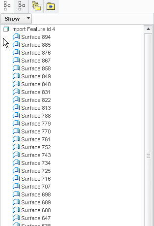
Click the icon indicated above to enter the IDD Editing Environment. Your model tree will then change. Instead of seeing one feature for your imported geometry, you'll see a series of individual surfaces... like this:
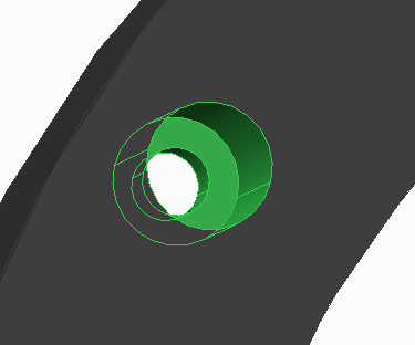
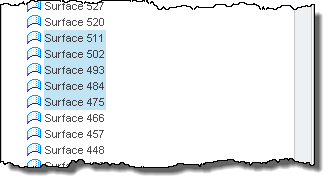
Once you're in this mode, you can select all the surfaces of the holes you wish to delete. In the image below, I've selected multiple surfaces. You can see from the model tree (below the model image) that the surfaces are being selected...
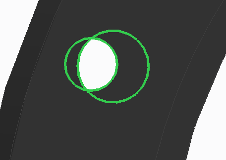
Right-click and select DELETE to remove these surfaces. You'll be left with open edges where the hole used to be. Next, you need to delete the profile/edges of the hole to complete the removal process. Note below, I've selected the open edges of the hole profile.
Finally, right-click and select DELETE again to remove these open edges. The hole has been successfully removed. You can now select the green check mark to exit out of the IDD mode. Your imported model will now appear without the hole. You can place a new hole wherever you'd like.
Hope that helped! If I've left something out, just ask!
Thanks!
-Brian
- Mark as New
- Bookmark
- Subscribe
- Mute
- Subscribe to RSS Feed
- Permalink
- Notify Moderator
Depending on software version, you should be able to fill in the hole and create new holes. If you have the flexible modeling extension, you can also move hole features.
You might also need to check to see if ATB is turned on. It will have a funny ICON (not the default "prt" icon) in front of the name in the tree. This may or may not restrict feature creation.
I am not sure when these capabilities were added, but I know in 2000i, it was nearly impossible to modify impported parts.
- Mark as New
- Bookmark
- Subscribe
- Mute
- Subscribe to RSS Feed
- Permalink
- Notify Moderator
Hi
I am using creo 1.0 and didnot find the flexible modeling
I have not idea about ATB
- Mark as New
- Bookmark
- Subscribe
- Mute
- Subscribe to RSS Feed
- Permalink
- Notify Moderator
Hi Raj...
The easiest way is, as Tom suggested, use Flexible Modeling to move the holes. If you don't have the FMX (Flexible Modeling Extension) to Creo, you'll have to go "old school" to remove the holes and then place them back in again at the desired location. ATB will be of no use for this problem.
Using the old school model editing methods, you will not be able to move the hole- you must delete it and make new ones. To get rid of the old holes, you'll need to enter the IDD (Import Data Doctor). To do this, edit definition on the imported feature. You'll see this set of icons appear on your menu... these are the icons used for the Import Data Doctor:

Click the icon indicated above to enter the IDD Editing Environment. Your model tree will then change. Instead of seeing one feature for your imported geometry, you'll see a series of individual surfaces... like this:

Once you're in this mode, you can select all the surfaces of the holes you wish to delete. In the image below, I've selected multiple surfaces. You can see from the model tree (below the model image) that the surfaces are being selected...


Right-click and select DELETE to remove these surfaces. You'll be left with open edges where the hole used to be. Next, you need to delete the profile/edges of the hole to complete the removal process. Note below, I've selected the open edges of the hole profile.

Finally, right-click and select DELETE again to remove these open edges. The hole has been successfully removed. You can now select the green check mark to exit out of the IDD mode. Your imported model will now appear without the hole. You can place a new hole wherever you'd like.
Hope that helped! If I've left something out, just ask!
Thanks!
-Brian
- Mark as New
- Bookmark
- Subscribe
- Mute
- Subscribe to RSS Feed
- Permalink
- Notify Moderator
thanks once again Brian
- Mark as New
- Bookmark
- Subscribe
- Mute
- Subscribe to RSS Feed
- Permalink
- Notify Moderator
but Brian how can I fill the gaps
I am able to del all the required surfaces but there are a empty space
may be boundry bend etc..??
- Mark as New
- Bookmark
- Subscribe
- Mute
- Subscribe to RSS Feed
- Permalink
- Notify Moderator
Hi Raj,
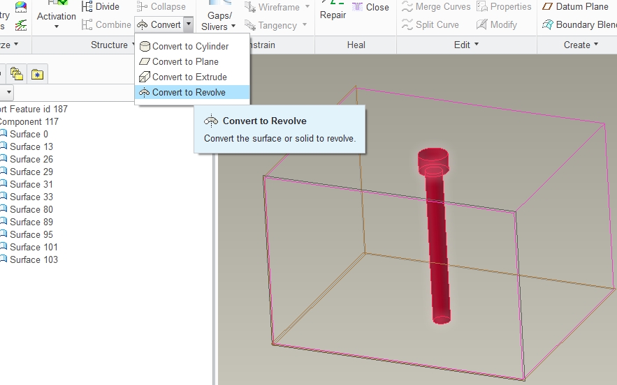
If you just want to move the holes to another place maybe you can convert them to Revolve features and place them where you want directly in the IDD.
First select the hole surfaces and CONVERT TO REVOLVE
Then just use the handle to dinamically move the surfaces or use the TWEAK DIRECTION tab for a more precise control.
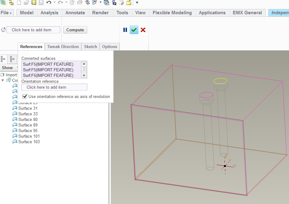
It will fill in the space that was once occupied by the surfaces you moved.
Hope this helps.
- Mark as New
- Bookmark
- Subscribe
- Mute
- Subscribe to RSS Feed
- Permalink
- Notify Moderator
Looks like the DataDoctor is a lot more powerful then I 1st gave it credit for.
- Mark as New
- Bookmark
- Subscribe
- Mute
- Subscribe to RSS Feed
- Permalink
- Notify Moderator
It wasn't always that powerful... just with Creo it's gotten much nicer!
- Mark as New
- Bookmark
- Subscribe
- Mute
- Subscribe to RSS Feed
- Permalink
- Notify Moderator
Excellent addition Antonio...
One word of caution... be careful as you dynamically move items around. It's possible to rotate holes that have been converted to revolves such that they are "out of plane". This can cause some odd looking geometry where a hole is detached from it's parent geometry.
- Mark as New
- Bookmark
- Subscribe
- Mute
- Subscribe to RSS Feed
- Permalink
- Notify Moderator
Yes Brian, you sure have to be careful especially when the surrounding surfaces are curved.
- Mark as New
- Bookmark
- Subscribe
- Mute
- Subscribe to RSS Feed
- Permalink
- Notify Moderator
Hi Raj...
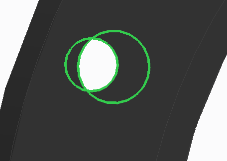
Once you delete the hole surfaces, you'll be left with gaps due to the hole boundaries. Remove those hole boundaries, too, and the gaps will "fill themselves in". That's what this picture was supposed to be showing... I picked the edges around the openings for the hole and removed them...
Of course, you can also try Antonio's method but it takes some practice to execute properly. This is about as close as you can get to using the flexible modeling tools without actually buying them!
Good luck!
-Brian
- Mark as New
- Bookmark
- Subscribe
- Mute
- Subscribe to RSS Feed
- Permalink
- Notify Moderator
Hi all,
the import data doctor offers yet another nice possibility (did this in WF4):
the surfaces to be moved are "devided" which will put them into a separate Component node under a Combine node.
Now when the hole surfaces are moved using the "Translate" command the boundries of the adjacent surfaces are recalculated as well.
However this only works if the moved surfaces and the adjacent surfaces with the according trim boundaries sit under the same Combine node.
After a "Collapse" you have a merged quilt.
- Mark as New
- Bookmark
- Subscribe
- Mute
- Subscribe to RSS Feed
- Permalink
- Notify Moderator
Thanks Constantin...
Nice! I hadn't tried that before.


