
Turn on suggestions
Auto-suggest helps you quickly narrow down your search results by suggesting possible matches as you type.
Showing results for
Please log in to access translation
Turn on suggestions
Auto-suggest helps you quickly narrow down your search results by suggesting possible matches as you type.
Showing results for
Community Tip - Your Friends List is a way to easily have access to the community members that you interact with the most! X
- Community
- Creo+ and Creo Parametric
- 3D Part & Assembly Design
- Re: Extending Datum Feature Symbols Beyond Referen...
Translate the entire conversation x
Please log in to access translation
Options
- Subscribe to RSS Feed
- Mark Topic as New
- Mark Topic as Read
- Float this Topic for Current User
- Bookmark
- Subscribe
- Mute
- Printer Friendly Page
Extending Datum Feature Symbols Beyond Reference Surface
Jul 13, 2018
12:23 PM
- Mark as New
- Bookmark
- Subscribe
- Mute
- Subscribe to RSS Feed
- Permalink
- Notify Moderator
Please log in to access translation
Jul 13, 2018
12:23 PM
Extending Datum Feature Symbols Beyond Reference Surface
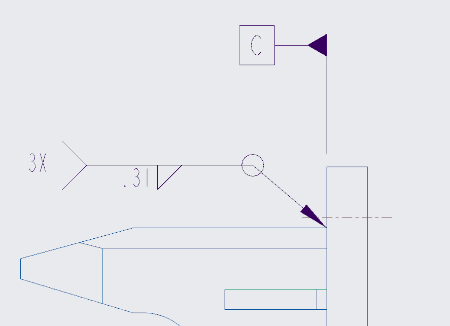
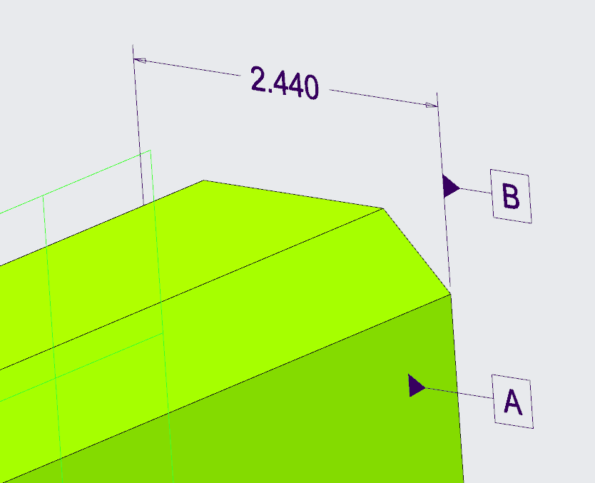
Is it possible to drag/move Datum Feature Symbol's beyond the referenced surface boundary? For example, the attached image show Datum A, and I'm not able to drag it beyond the surface perimeter.
The best work-around I can find is to attach the DFS to a dimension witness line, but that's undesirable because I then have to go back and add the surface as a reference. I'd like to be able to move a DFS beyond the referenced surface similar to the attached drawing image. I'm currently using Creo 4 M040, but have tested this in Creo 5 M000, and the behavior is the same.
Labels:
- Labels:
-
MBD_GD&T
14 REPLIES 14
Jul 16, 2018
10:21 AM
- Mark as New
- Bookmark
- Subscribe
- Mute
- Subscribe to RSS Feed
- Permalink
- Notify Moderator
Please log in to access translation
Jul 16, 2018
10:21 AM
Looks like you're going to need to create a product idea. PTC tech support is saying this is not currently possible.
"The current behavior is working as per the specification for Creo Parametric. It is not possible to move the DFS beyond the boundary of the selected/referenced surface."
Jul 16, 2018
10:28 AM
- Mark as New
- Bookmark
- Subscribe
- Mute
- Subscribe to RSS Feed
- Permalink
- Notify Moderator
Please log in to access translation
Jul 16, 2018
10:28 AM
Thanks for the follow-up.
Jul 16, 2018
10:33 AM
- Mark as New
- Bookmark
- Subscribe
- Mute
- Subscribe to RSS Feed
- Permalink
- Notify Moderator
Please log in to access translation
Jul 16, 2018
10:33 AM
This is such a common use case, I'm surprised it's not possible. A quick glance at Y14.5-2009 shows dozens of examples of DFS's positioned this way.
Jul 16, 2018
10:42 AM
- Mark as New
- Bookmark
- Subscribe
- Mute
- Subscribe to RSS Feed
- Permalink
- Notify Moderator
Please log in to access translation
Jul 16, 2018
10:42 AM
Yeah, I don't get it either...
Jul 16, 2018
11:03 AM
- Mark as New
- Bookmark
- Subscribe
- Mute
- Subscribe to RSS Feed
- Permalink
- Notify Moderator
Please log in to access translation
Jul 16, 2018
11:03 AM
This video from PTC shows it as a possbility (but not how to do it). I have opened a ticket to ask how they did it. I will post when I hear from them. Its possible it is not attached to a surface in the video.
")
Learn how Creo 4.0 enables more intuitive workflows for creating and editing geometric tolerances (GTOLS) in drawings. ▬▬▬▬▬ Connect with PTC ► YouTube: @ptc ► LinkedIn: https://linkedin.com/company/ptcinc ► Facebook: https://facebook.com/ptc.inc ► Twitter: https://twitter.com/PTC ► Instagram: ...
Jul 16, 2018
11:13 AM
- Mark as New
- Bookmark
- Subscribe
- Mute
- Subscribe to RSS Feed
- Permalink
- Notify Moderator
Please log in to access translation
Jul 16, 2018
11:13 AM
Chris3 -- If you create a draft DFS in a drawing, you can position it appropriately, as shown with Datum A in the video you posted. Unfortunately, this capability isn't available in modeling mode.
Jul 16, 2018
11:21 AM
- Mark as New
- Bookmark
- Subscribe
- Mute
- Subscribe to RSS Feed
- Permalink
- Notify Moderator
Please log in to access translation
Jul 16, 2018
11:21 AM
If you watch the video at 1:02 the typed in datum -A- goes green which means that the datum tag is in the model. If the datum tag was defined in the drawing it would not have changed to green.
Its possible I am missing something though. I am still figuring it out myself.
Jul 18, 2018
03:17 PM
- Mark as New
- Bookmark
- Subscribe
- Mute
- Subscribe to RSS Feed
- Permalink
- Notify Moderator
Please log in to access translation
Jul 18, 2018
03:17 PM
I got the same answer from PTC. This is only possible with datum feature symbols created in the drawing or set datums but those can not be parametrically tied to the Gtol. I have created an idea for this because no one else has yet.
Aug 14, 2018
12:23 PM
- Mark as New
- Bookmark
- Subscribe
- Mute
- Subscribe to RSS Feed
- Permalink
- Notify Moderator
Please log in to access translation
Aug 14, 2018
12:23 PM
PTC has added this capability to Creo Parametric 4.0 M060. It is now possible to drag a datum feature symbol created in the model past the boundary of the referenced surface in the drawing.
Here is the official verbiage from CS251133:
"The placement of annotations in drawings is enhanced. You can drag the annotation beyond the surface boundary in drawings, providing more flexibility."
Here is a video showing the new behavior:
Aug 14, 2018
01:45 PM
- Mark as New
- Bookmark
- Subscribe
- Mute
- Subscribe to RSS Feed
- Permalink
- Notify Moderator
Please log in to access translation
Aug 14, 2018
01:45 PM
Thanks @TomU. When I do it I get a dashed line. Did you do something to make the leader line solid?
Aug 14, 2018
02:44 PM
- Mark as New
- Bookmark
- Subscribe
- Mute
- Subscribe to RSS Feed
- Permalink
- Notify Moderator
Please log in to access translation
Aug 14, 2018
02:44 PM
Without digging into it I would guess it's a detail option setting in the drawing. I've attached a copy of our settings to this post. Maybe do a side by side comparison with yours and see what's different. (WinMerge is great for this.)
Aug 15, 2018
06:51 AM
- Mark as New
- Bookmark
- Subscribe
- Mute
- Subscribe to RSS Feed
- Permalink
- Notify Moderator
Please log in to access translation
Aug 15, 2018
06:51 AM
Thanks!
The option was
leader_extension_font SOLIDFONT
which is the default.
Jun 11, 2020
12:12 PM
- Mark as New
- Bookmark
- Subscribe
- Mute
- Subscribe to RSS Feed
- Permalink
- Notify Moderator
Please log in to access translation
Jun 11, 2020
12:12 PM
That didn't work for me when I tried it in M140, but you can show a dimension in the annotation tab, then attach a datum to one of its witness lines, and it will appear in the drawing the same way.
- Tags:
- hat doesn't work
Aug 22, 2018
10:01 AM
- Mark as New
- Bookmark
- Subscribe
- Mute
- Subscribe to RSS Feed
- Permalink
- Notify Moderator
Please log in to access translation
Aug 22, 2018
10:01 AM
Hello,
This is Michael Fridman, the new product manager for MBD & Detailing at PTC.
I can update you that in Creo 4.0 M060 we have enhanced this behavior on the drawing side. so now you can drag the DFS in the corresponding view out of the boundary.
On the model (or MBD) this will maintain as is for now.
Hope this helps


