
Turn on suggestions
Auto-suggest helps you quickly narrow down your search results by suggesting possible matches as you type.
Showing results for
Please log in to access translation
Turn on suggestions
Auto-suggest helps you quickly narrow down your search results by suggesting possible matches as you type.
Showing results for
Community Tip - You can Bookmark boards, posts or articles that you'd like to access again easily! X
- Community
- Creo+ and Creo Parametric
- 3D Part & Assembly Design
- Feature Parameters into Drawing Note
Translate the entire conversation x
Please log in to access translation
Options
- Subscribe to RSS Feed
- Mark Topic as New
- Mark Topic as Read
- Float this Topic for Current User
- Bookmark
- Subscribe
- Mute
- Printer Friendly Page
Feature Parameters into Drawing Note
Oct 01, 2015
10:15 AM
- Mark as New
- Bookmark
- Subscribe
- Mute
- Subscribe to RSS Feed
- Permalink
- Notify Moderator
Please log in to access translation
Oct 01, 2015
10:15 AM
Feature Parameters into Drawing Note
Hello,
I want to make use of the FLAT_PATTERN_WIDTH and FLAT_PATTERN_LENGTH parameters generated by created a flat pattern in my models.
Is there a way to create a drawing note that references these feature parameters with each new model? The method I've tried is feature ID specific, so a standard note needs to be updated to each unique feature ID.
(see this discussion: New feature parameters in sheetmetal
Thanks in advance!
Brandon
This thread is inactive and closed by the PTC Community Management Team. If you would like to provide a reply and re-open this thread, please notify the moderator and reference the thread. You may also use "Start a topic" button to ask a new question. Please be sure to include what version of the PTC product you are using so another community member knowledgeable about your version may be able to assist.
Solved! Go to Solution.
Labels:
- Labels:
-
General
ACCEPTED SOLUTION
Accepted Solutions
Oct 01, 2015
12:32 PM
- Mark as New
- Bookmark
- Subscribe
- Mute
- Subscribe to RSS Feed
- Permalink
- Notify Moderator
Please log in to access translation
Oct 01, 2015
12:32 PM
I take it you have one such feature in your model, because otherwise having it in the title block wouldn't make sense. So here's an idea (which I've confirmed works with an ordinary feature with parameters, but haven't tried to make a SMT flat pattern). The main goal here is to never have to enter the feature ID or name.
1) In the feature, you have parameters SMT_FLAT_PATTERN_WIDTH / SMT_FLAT_PATTERN_LENGTH.
2) Make parameters MY_FLATPAT_WIDTH and MY_FLATPAT_LENGTH in the solid.
3) Tools>Relations>Feature>[the flat pattern], enter:
my_flatpat_width=smt_flat_pattern_width
my_flatpat_length=smt_flat_pattern_length
4) Have the title block note use &my_flatpat_width and &my_flatpat_length to get the params from the part.
Try it out?
9 REPLIES 9
Oct 01, 2015
12:19 PM
- Mark as New
- Bookmark
- Subscribe
- Mute
- Subscribe to RSS Feed
- Permalink
- Notify Moderator
Please log in to access translation
Oct 01, 2015
12:19 PM
You can also use the feature name instead of the feature ID. If your feature naming is consistent, then it seems like this would work. The drawing will resolve the name to the ID after it finds it, but it's worth a shot.
Something like &FLAT_PATTERN_WIDTH:FID_FLAT_PATTERN where FLAT_PATTERN is the feature name.
Full disclaimer: I didn't actually test this method, just shooting from the hip...
Oct 06, 2015
08:02 AM
- Mark as New
- Bookmark
- Subscribe
- Mute
- Subscribe to RSS Feed
- Permalink
- Notify Moderator
Please log in to access translation
Oct 06, 2015
08:02 AM
I tried the feature name method; see Mathew Ender's reply. No luck. Relations editor only accepts the lines with the feature ID included.
Thanks for the reply.
Oct 01, 2015
12:32 PM
- Mark as New
- Bookmark
- Subscribe
- Mute
- Subscribe to RSS Feed
- Permalink
- Notify Moderator
Please log in to access translation
Oct 01, 2015
12:32 PM
I take it you have one such feature in your model, because otherwise having it in the title block wouldn't make sense. So here's an idea (which I've confirmed works with an ordinary feature with parameters, but haven't tried to make a SMT flat pattern). The main goal here is to never have to enter the feature ID or name.
1) In the feature, you have parameters SMT_FLAT_PATTERN_WIDTH / SMT_FLAT_PATTERN_LENGTH.
2) Make parameters MY_FLATPAT_WIDTH and MY_FLATPAT_LENGTH in the solid.
3) Tools>Relations>Feature>[the flat pattern], enter:
my_flatpat_width=smt_flat_pattern_width
my_flatpat_length=smt_flat_pattern_length
4) Have the title block note use &my_flatpat_width and &my_flatpat_length to get the params from the part.
Try it out?
Oct 06, 2015
07:58 AM
- Mark as New
- Bookmark
- Subscribe
- Mute
- Subscribe to RSS Feed
- Permalink
- Notify Moderator
Please log in to access translation
Oct 06, 2015
07:58 AM
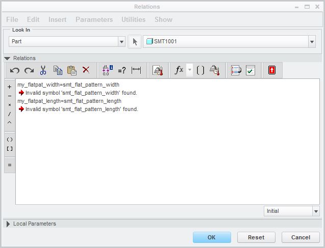
I gave this method a shot. Seems like it should work, but without the feature ID, the relations editor gives me an error. Maybe sheetmetal flat pattern parameters are different than other features.
See attached pics.
Oct 06, 2015
08:25 AM
- Mark as New
- Bookmark
- Subscribe
- Mute
- Subscribe to RSS Feed
- Permalink
- Notify Moderator
Please log in to access translation
Oct 06, 2015
08:25 AM
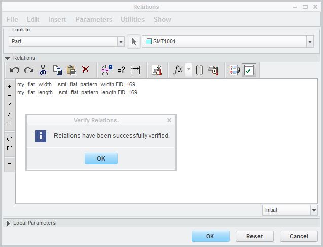
The problem is that you are making the relations in the part, not in the feature. "By Tools>Relations>Feature>[the flat pattern]", I mean where it says 'Look In: Part' in the upper left, to select Feature, and pick the flat pattern. The part level relations can get at info from any feature, but would indeed need to name the feature to do so.
Oct 06, 2015
08:40 AM
- Mark as New
- Bookmark
- Subscribe
- Mute
- Subscribe to RSS Feed
- Permalink
- Notify Moderator
Please log in to access translation
Oct 06, 2015
08:40 AM
Ok, that makes sense. It appears that the flat pattern automatically creates those feature paramaters. How do I summon those in a drawing note?
Using the note next that I would for normal part parameters doesn't work: &smt_flat_pattern_width.
Adding the feature ID does work this way &smt_flat_pattern_width:fid_169
Oct 06, 2015
08:52 AM
- Mark as New
- Bookmark
- Subscribe
- Mute
- Subscribe to RSS Feed
- Permalink
- Notify Moderator
Please log in to access translation
Oct 06, 2015
08:52 AM
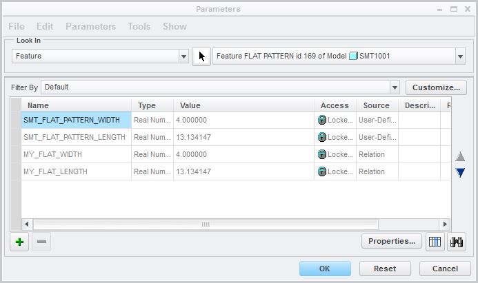
Again, it's a question of relations/parameters context. When I said "2) Make parameters MY_FLATPAT_WIDTH and MY_FLATPAT_LENGTH in the solid." I mean, Tools>Parameters, Look in: Part. These parameters are to be at the part level. Also note they need to exist before you add the relation at the feature level.
Oct 06, 2015
09:13 AM
- Mark as New
- Bookmark
- Subscribe
- Mute
- Subscribe to RSS Feed
- Permalink
- Notify Moderator
Please log in to access translation
Oct 06, 2015
09:13 AM
Ok, that makes sense. I'm new to custom relations and parameters, so thanks for your patience.
Your process works fine. The last problem is I can't have this preloaded into a sheetmetal startpart as a flat pattern needs to be present, which creates the feature parameters smt_flat_pattern_width & _length. Is this corrrect?
I could create a mapkey to be executed sometime after the part and flat pattern are present.
Brandon
Oct 06, 2015
09:21 AM
- Mark as New
- Bookmark
- Subscribe
- Mute
- Subscribe to RSS Feed
- Permalink
- Notify Moderator
Please log in to access translation
Oct 06, 2015
09:21 AM
Preloading, hmm... The part level parameters can be made in your start part, but unless the flat pattern is in the start part, indeed you'll need to put them in when the feature is made.


