- Community
- Creo+ and Creo Parametric
- 3D Part & Assembly Design
- Re: Flatten?
- Subscribe to RSS Feed
- Mark Topic as New
- Mark Topic as Read
- Float this Topic for Current User
- Bookmark
- Subscribe
- Mute
- Printer Friendly Page
Flatten?
- Mark as New
- Bookmark
- Subscribe
- Mute
- Subscribe to RSS Feed
- Permalink
- Notify Moderator
Flatten?
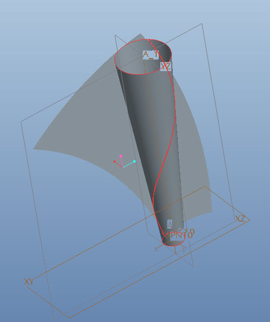
Cone shape. 2" on one side 5" on the other, and about 24" apart. Helical cut with a pitch of 24. Surface or sheetmetal doesnt matter to me. The questions is can I flatten it?
Solved! Go to Solution.
Accepted Solutions
- Mark as New
- Bookmark
- Subscribe
- Mute
- Subscribe to RSS Feed
- Permalink
- Notify Moderator
How about:
1. Revolved surface
2. Insert - Helical Sweep - Thin Surface trim
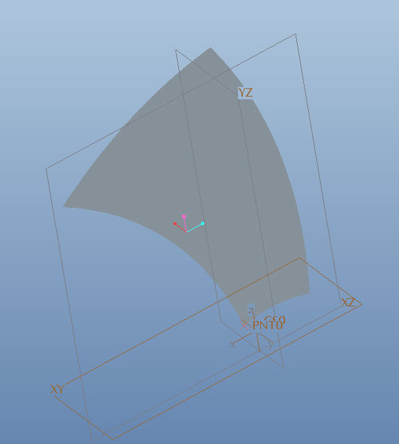
3. Insert - Advanced - Flatten Quilt


- Mark as New
- Bookmark
- Subscribe
- Mute
- Subscribe to RSS Feed
- Permalink
- Notify Moderator
Hi Craig...
I have your geometry... I'll see what I can come up with tonight. I was almost able to flatten a similar geometry early today. I'll take another run at it.
Thanks!
-Brian
- Mark as New
- Bookmark
- Subscribe
- Mute
- Subscribe to RSS Feed
- Permalink
- Notify Moderator
Hi Craig...
:Sigh: I always hate to say never when it applies to Pro/E or Creo because there's USUALLY a way to create anything you need. Sometimes the technique to get there is hopelessly complex ... but it usually exists. I can't rule out that there's some strange method of creating the geometry you're describing. However, I've exhausted every reasonable possibility and I can't get it to work.
For reference, here's what I tried.
[1] Cone created as a simple blend and helical cut (1 turn /pitch of 24) as you described:
- Tried flattening the cone with an inverse Spinal Bend - Failed
- Tried flattening the cone with a sophisticated Warp command - Failed
- Tried flattening the cone in sheetmetal mode - Failed
[2] Cone created as a surface blend with a simple cut (as a test)
- Tried to use Flatten Quilt to flatten the surface - failed due to tangency issues. I was unable to resolve any of the tangency issues no matter what I tried
[3] Cone created as a revolved sheet metal piece (conical) with a helical cut
- Could not flatten piece due to inability to create rip.
- In an attempt to create a Rip I tried:
- Adding a Curve by Equation using a cylindrical coordinate system. This created a helical curve which was mapped directly to the surface of the cone.
- Added points to the helical curve and patterned them
- Attempted to use points along the curve as point relief and/or Rip Connect points using the Sheet Metal Conversion feature - Failed.
[4] Cone created as a Swept Blend - all attempts to flatten using above techniques Failed
[5] Cone created as a Rotational Blend using semi-circular sections. Imagine a 359 degree circle with thickness of .06" (slight 1 degree gap). I made one section 5" in diameter and another 2" in diameter. I set them 24" apart and used a Rotational Blend to twist them 360 degrees out of phase. The small gap represented the material removed by the helical cut. This is a pretty slick technique... but it Failed.
In fact, the ONLY thing that seemed to work was a Regular Rip. I could successfully sketch a Regular Rip (as long as it was planar) and unbend the cone. Even when I tried to make a series of smaller planar rips to approximate a helical cut, the object would not flatten.
I cranked the model accuracy. I tried making the geometry in solid and sheet metal modes. I even tried sketching the geometry flat in sheet metal mode and then rolling it into a spiral using Bend>Roll. This technique showed promise until the cylinder rolled back onto itself. The PTC documentation suggests you can roll sheet metal into a spiral as long as the geometry doesn't TOUCH itself (self-intersect). This is not true. If the geometry rolls more than 360 degrees it fails even if the geometry is not self-intersecting.
About the only thing left to do would be to draw the flat form of the cone and then use a Spinal Bend or Warp>Bend feature to roll it up into a cone again. This requires you to know the flat shape of the geometry FIRST before you create the cone. While you could probably come up with some sketches to capture the conical dimensions and then use those sketches to calculate and create your flat geometry, it doesn't seem worth it.
If the point is to take a conical shaped piece of sheet metal and have Pro/E flatten it... then you're pretty much stuck. I can't do it... and I am out of reasonable ideas to investigate. I'd bet the Mathcad guys could calculate the flat pattern... but I don't see an easy way to do this in Pro/ENGINEER.
Also... FYI, I investigated and SolidWorks can't do it either. SolidWorks, for all it's faults, has a sheet metal package that rivals that of Pro/ENGINEER. I don't like admitting that, but it's true. Still, even SolidWorks couldn't tackle this problem. I suspect we're asking the software to do something that is currently beyond it's capabilities.
I'm sorry I don't have a better answer. 😕 Maybe someone else can take a crack at it??
Thanks!
-Brian
- Mark as New
- Bookmark
- Subscribe
- Mute
- Subscribe to RSS Feed
- Permalink
- Notify Moderator
Well I probably tried ½ of the same techniques you used and came up with the same results. I also tried it in a couple of other software, and with no surprise had the same results. It would be nice if someone could just tell us it can’t be done so I can stop wasting time on it!!!
- Mark as New
- Bookmark
- Subscribe
- Mute
- Subscribe to RSS Feed
- Permalink
- Notify Moderator
How about:
1. Revolved surface
2. Insert - Helical Sweep - Thin Surface trim
3. Insert - Advanced - Flatten Quilt


- Mark as New
- Bookmark
- Subscribe
- Mute
- Subscribe to RSS Feed
- Permalink
- Notify Moderator
Egad... revolved surface. That's certainly one I didn't try.
And see... this is why I try to NEVER say something "can't be done in Pro/E" because if you perservere and keep trying different techniques, sometimes you hit paydirt!
I believe the issue here isn't so much HOW the surface is made (because I tried multiple surfaces with the flatten quilt feature). I believe it's the way the trim is created- PLUS you can't have any thickness to your quilt. For instance, I tried a surface with thickness and "capped ends"... this failed. Starting with a thin surface, flattening, and then using thicken to give the surface depth is probably the way to go. You can then Bend Solid (i'm assuming) and get the cone you're after.
Very nice Jorgen!! Thanks for the response!!
Regards,
-Brian
- Mark as New
- Bookmark
- Subscribe
- Mute
- Subscribe to RSS Feed
- Permalink
- Notify Moderator
So I got around to testing the flatten. I did the revolve surface, then a helical thin surface trim. I still cant get that surface to flatten. I have the method set to Automatic… I have datum points in all 4 corners that I have tested… What am I missing????
- Mark as New
- Bookmark
- Subscribe
- Mute
- Subscribe to RSS Feed
- Permalink
- Notify Moderator
Is it possible to create similar part except with gaps between each roll of the sheet metal? Still maintain the same concept.


