
Turn on suggestions
Auto-suggest helps you quickly narrow down your search results by suggesting possible matches as you type.
Showing results for
Please log in to access translation
Turn on suggestions
Auto-suggest helps you quickly narrow down your search results by suggesting possible matches as you type.
Showing results for
Community Tip - Want the oppurtunity to discuss enhancements to PTC products? Join a working group! X
- Community
- Creo+ and Creo Parametric
- 3D Part & Assembly Design
- Re: Help...Section view on assembly drawing issue
Translate the entire conversation x
Please log in to access translation
Options
- Subscribe to RSS Feed
- Mark Topic as New
- Mark Topic as Read
- Float this Topic for Current User
- Bookmark
- Subscribe
- Mute
- Printer Friendly Page
Help...Section view on assembly drawing issue
Mar 18, 2021
10:51 AM
- Mark as New
- Bookmark
- Subscribe
- Mute
- Subscribe to RSS Feed
- Permalink
- Notify Moderator
Please log in to access translation
Mar 18, 2021
10:51 AM
Help...Section view on assembly drawing issue
Hi all,
I have an issue where on a 2D assembly drawing, the view shows lines that shouldn't be there.
It's not all lines, some are not visible but some are - see the attached example.
How do i stop this happening?
It's probably an easy fix.....
Labels:
- Labels:
-
2D Drawing
10 REPLIES 10
Mar 18, 2021
11:45 AM
- Mark as New
- Bookmark
- Subscribe
- Mute
- Subscribe to RSS Feed
- Permalink
- Notify Moderator
Please log in to access translation
Mar 18, 2021
11:45 AM
Can't view this because we can't open .docx files from outside sources.
If you're doing a view of an assembly and lines that should be there are not, or vice versa, it can usually be one of these things:
(1) There's interference between two parts. For example, a pin is 0.5000 diameter, but the hole it's going into is 0.4990 diameter. Creo will decide to omit lines at the interference, but not consistently.
(2) Sections that have been defined in previous versions of Creo, maybe even a previous build code, will not interpret section views correctly. It might be the definition of the view direction in the part/assembly. Unfortunately, I usually find that the only way to fix this is to take the section out of the view, finish editing the view properties, then edit the view properties again and add the section back in. I hate it, but it usually works.
Mar 18, 2021
11:53 AM
- Mark as New
- Bookmark
- Subscribe
- Mute
- Subscribe to RSS Feed
- Permalink
- Notify Moderator
Please log in to access translation
Mar 18, 2021
11:53 AM
What does the model look like with the section active? A screen shot of the model would help us to determine what is going on.
Is everything solid?
There is always more to learn in Creo.
Mar 19, 2021
05:26 AM
- Mark as New
- Bookmark
- Subscribe
- Mute
- Subscribe to RSS Feed
- Permalink
- Notify Moderator
Please log in to access translation
Mar 31, 2021
06:59 AM
- Mark as New
- Bookmark
- Subscribe
- Mute
- Subscribe to RSS Feed
- Permalink
- Notify Moderator
Please log in to access translation
Mar 31, 2021
06:59 AM
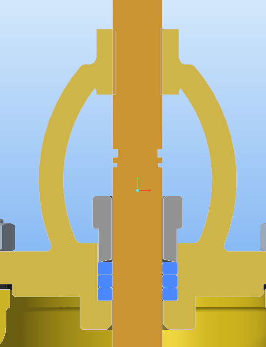
The intersection of the gold outer part with the bronze center post part is what I'm talking about. There is an interference between the two. I'm guessing because the gold part is modeled with the minor diameter of a thread? This kind of thing throws the hidden line removal and section display algorithms off, so you get strange depictions of the crosshatching.
Sometimes, when I'm troubled by it enough, I'll fix these types of things by having a family table version of the part with the holes in it where the hole diameters are suitable to prevent this kind of thing. That version of the part is only used in the assembly, while the part that is depicted in drawings and/or used in manufacturing is the "actual" correct geometry. It complicates things a bit, but if I want those views to look right I'm willing to suffer the extra trouble.
Mar 18, 2021
11:56 AM
- Mark as New
- Bookmark
- Subscribe
- Mute
- Subscribe to RSS Feed
- Permalink
- Notify Moderator
Please log in to access translation
Mar 18, 2021
11:56 AM
This part looks like it has cosmetic thread lines which are visible, not the solid lines
Pushkar
Mar 19, 2021
05:27 AM
- Mark as New
- Bookmark
- Subscribe
- Mute
- Subscribe to RSS Feed
- Permalink
- Notify Moderator
Please log in to access translation
Mar 19, 2021
05:27 AM
Yes some of them are.
How do i hide them?
Mar 31, 2021
06:46 AM
- Mark as New
- Bookmark
- Subscribe
- Mute
- Subscribe to RSS Feed
- Permalink
- Notify Moderator
Please log in to access translation
Mar 31, 2021
06:46 AM
Is it possible there is a cosmetic thread there? Or any other line that would show up on the wireframe?
Mar 31, 2021
06:58 AM
- Mark as New
- Bookmark
- Subscribe
- Mute
- Subscribe to RSS Feed
- Permalink
- Notify Moderator
Please log in to access translation
Mar 31, 2021
06:58 AM
Yes, there is a cosmetic thread there.
Mar 31, 2021
07:00 AM
- Mark as New
- Bookmark
- Subscribe
- Mute
- Subscribe to RSS Feed
- Permalink
- Notify Moderator
Please log in to access translation
Mar 31, 2021
07:00 AM
Try hiding the cosmetic thread, see what happens, and if you have to put it on layer and hide it.
Mar 31, 2021
07:34 AM
- Mark as New
- Bookmark
- Subscribe
- Mute
- Subscribe to RSS Feed
- Permalink
- Notify Moderator
Please log in to access translation
Mar 31, 2021
07:34 AM
- Create new layer on part enviroment, include only the cosmeti thread.
- In the drawing select layer tree, select the view where you want to hide the cosmetic thread and save the status of the layers


