Community Tip - If community subscription notifications are filling up your inbox you can set up a daily digest and get all your notifications in a single email. X
- Community
- Creo+ and Creo Parametric
- 3D Part & Assembly Design
- Re: How to correctly sweep through this curve?
- Subscribe to RSS Feed
- Mark Topic as New
- Mark Topic as Read
- Float this Topic for Current User
- Bookmark
- Subscribe
- Mute
- Printer Friendly Page
How to correctly sweep through this curve?
- Mark as New
- Bookmark
- Subscribe
- Mute
- Subscribe to RSS Feed
- Permalink
- Notify Moderator
How to correctly sweep through this curve?
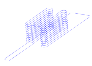
Made this curve through points, it supposed to be a conveyor belt
When i tried to make a simple sweep, drew a rectangle at the starting point, it swept it along the trajectory by rotating the rectangle, based on the curve's direction. So the rectanlge didn't remain normal , and I couldn't figure out which setting to use
So the question, how can I make this sweep, so the rectangles sides stay normal to something, and doesnt rotate?
Or is there an alternative way to do this? I just want a rectangle section along the curve
Here's the file : files.fm/u/dpqvzrxw#
Thanks!!
- Mark as New
- Bookmark
- Subscribe
- Mute
- Subscribe to RSS Feed
- Permalink
- Notify Moderator
Hi, did you find any solution to this problem?
I know it's been 7 years, but I have a similar problem with control of my sweep and preventing an unexpected twist.
- Mark as New
- Bookmark
- Subscribe
- Mute
- Subscribe to RSS Feed
- Permalink
- Notify Moderator
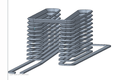
Set "Section plane control" to "Normal To Projection" in sweep References.
And set datum plane witch will define orientation for sweep section.
- Mark as New
- Bookmark
- Subscribe
- Mute
- Subscribe to RSS Feed
- Permalink
- Notify Moderator
@Van_AG thank you , but can you please be more specific? I have about 25 planes in this design, I know you don't see them.
That rectangle must be rotated 90 deg, so the angle that now has 51.9155 deg should have 90 deg and the other one should have 0 deg.
I'm not sure which datum plane to pick as it doesn't generate anything when I do. It doesn't allow me to sketch the profile anything when I do.

1 must be parallel to 2 and right angle between 3 & 4. The turn to bottom left must be flat as well, with the bigger surface on the top.
- Mark as New
- Bookmark
- Subscribe
- Mute
- Subscribe to RSS Feed
- Permalink
- Notify Moderator
Can you share the trajectory curve please.
I'll try to explain
- Mark as New
- Bookmark
- Subscribe
- Mute
- Subscribe to RSS Feed
- Permalink
- Notify Moderator
- Mark as New
- Bookmark
- Subscribe
- Mute
- Subscribe to RSS Feed
- Permalink
- Notify Moderator
Please see the attached models.
Trajectory segments "Intersect 1" and "Intersect 2" not tangent to neighbors, so I recreate them in r3-model
- Mark as New
- Bookmark
- Subscribe
- Mute
- Subscribe to RSS Feed
- Permalink
- Notify Moderator
Thank's @Van_AG it does look lovely now.
Can you expand on the steps so we all can understand what is the process please?
I see what you did, but since this tool is new to me, I don't quite understand HOW did you do it 😊
I see that you have created additional sections in here, and set them up to main XY plane, great move.
I suppose, this is what you mean by setting the tangency? This tool seems to be a very powerful one. Can you guide us to some extensive tutorial perhaps?
- Mark as New
- Bookmark
- Subscribe
- Mute
- Subscribe to RSS Feed
- Permalink
- Notify Moderator
I would encourage you to create a new thread specific to your model and issue. I have posted here an example of how to manage the trajectory of the corners which I think provides what you are looking for. In general, one would like to have a minimum of G1 (tangency) continuity along the entire sweep trajectory. With less than G1 continuity in the trajectory it usually results in undesired geometry when used for sweeps.
I have enclosed a model (Creo 4) where I have "managed" the corner transitions in a way that imposes tangency such that you can use the sweep normal to trajectory option to get a "good" corner transition. Note the corner has a single tangent transition where the two radii meet in 3D space.
Involute Development, LLC
Consulting Engineers
Specialists in Creo Parametric
- Mark as New
- Bookmark
- Subscribe
- Mute
- Subscribe to RSS Feed
- Permalink
- Notify Moderator
Illustration of corner control using two radii. This paradigm can of course be implemented for splines and 3D curves (ISDX) to get a desired transition in the corner as well. It is possible to impose continuity at G2 and G3 in some cases if needed.
Involute Development, LLC
Consulting Engineers
Specialists in Creo Parametric
- Mark as New
- Bookmark
- Subscribe
- Mute
- Subscribe to RSS Feed
- Permalink
- Notify Moderator
I have tried that before as you can see in my model. There is a tricky part because a sum of radiuses can't be higher that distance from bottom to top trajectories. If the sum is lower, then one can generate a intersection path.
- Mark as New
- Bookmark
- Subscribe
- Mute
- Subscribe to RSS Feed
- Permalink
- Notify Moderator
Thanks for the model and explanation. They look fine. In my model it is rather a feature than an error 😉.
Can you explain, how did you generate Section1 in your model please? I can see this, but my guess is that it comes from Curve from Cross Section. Please confirm if that is the case.
- Mark as New
- Bookmark
- Subscribe
- Mute
- Subscribe to RSS Feed
- Permalink
- Notify Moderator
I do not understand what section you are asking about (section 1). If you are asking about a specific feature, what feature #? I did not use curve from cross section when building the model.
The sketches used for the surface extrusions were manually sketched.
Involute Development, LLC
Consulting Engineers
Specialists in Creo Parametric


