
Turn on suggestions
Auto-suggest helps you quickly narrow down your search results by suggesting possible matches as you type.
Showing results for
Please log in to access translation
Turn on suggestions
Auto-suggest helps you quickly narrow down your search results by suggesting possible matches as you type.
Showing results for
Community Tip - Want the oppurtunity to discuss enhancements to PTC products? Join a working group! X
- Community
- Creo+ and Creo Parametric
- 3D Part & Assembly Design
- RE: plastic tolerancing issue...
Translate the entire conversation x
Please log in to access translation
Options
- Subscribe to RSS Feed
- Mark Topic as New
- Mark Topic as Read
- Float this Topic for Current User
- Bookmark
- Subscribe
- Mute
- Printer Friendly Page
Message I don't know what it means, can not paginate
Sep 04, 2012
05:45 PM
- Mark as New
- Bookmark
- Subscribe
- Mute
- Subscribe to RSS Feed
- Permalink
- Notify Moderator
Please log in to access translation
Sep 04, 2012
05:45 PM
Message I don't know what it means, can not paginate
Searched ptc.com and couldn't find what this refers to;
On loading a drawing I get the following lines in the message bar;
Can not paginate. Restore the previous extent.
Can not restore the previous extent.
huh?
This thread is inactive and closed by the PTC Community Management Team. If you would like to provide a reply and re-open this thread, please notify the moderator and reference the thread. You may also use "Start a topic" button to ask a new question. Please be sure to include what version of the PTC product you are using so another community member knowledgeable about your version may be able to assist.
Labels:
- Labels:
-
2D Drawing
10 REPLIES 10
Sep 04, 2012
05:59 PM
- Mark as New
- Bookmark
- Subscribe
- Mute
- Subscribe to RSS Feed
- Permalink
- Notify Moderator
Please log in to access translation
Sep 04, 2012
05:59 PM
On 09/04/12 16:45, Michael Gamber wrote:
> Searched ptc.com <">http://ptc.com> and couldn't find what this refers to;
>
> On loading a drawing I get the following lines in the message bar;
>
> Can not paginate. Restore the previous extent.
> Can not restore the previous extent.
Sounds like you have a bom repeat region with fixed extents (fixed number of table rows) and you now have more components than you have table rows to put them in.
You haven't specified what release of Pro/Engineer you are running however in Wildfire 5 to "clear the extents setting" you would do the following:
1. Select the table tab
2. select a cell from the affected repeat region
3. select the "Paginate..." icon
4. select "Clear Extent" from the menu manager
>
> huh?
>
> ----------
--
------------------------------------------------------------------------
Randy Jones
Systems Administrator
Great Plains Mfg., Inc.
1525 E North St
PO Box 5060
Salina, KS USA 67401
email: -
Phone: 785-823-3276
Fax: 785-667-2695
------------------------------------------------------------------------
Sep 04, 2012
06:02 PM
- Mark as New
- Bookmark
- Subscribe
- Mute
- Subscribe to RSS Feed
- Permalink
- Notify Moderator
Please log in to access translation
Sep 04, 2012
06:02 PM
Creo 2.0 M020
Went thru all my drawing pages and did the clear extents thing... Still get
the message. Weird, maybe one of the tables in my drawing format.
Will keep looking.
Went thru all my drawing pages and did the clear extents thing... Still get
the message. Weird, maybe one of the tables in my drawing format.
Will keep looking.
Sep 05, 2012
11:47 AM
- Mark as New
- Bookmark
- Subscribe
- Mute
- Subscribe to RSS Feed
- Permalink
- Notify Moderator
Please log in to access translation
Sep 05, 2012
11:47 AM
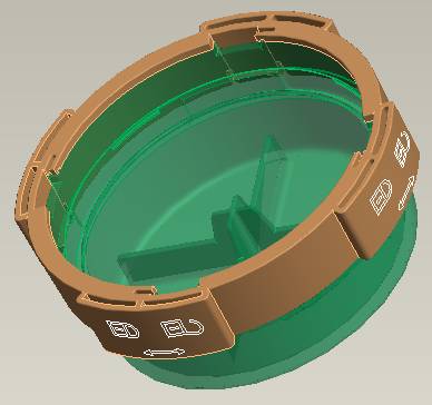
I don't' have much plastic injection molding experience so I was
wondering of you all could help me...
I've created a lid with a sliding lock ring that attaches to it shown
below. The surfaces between them are both drafted (in the same
direction) and I've added a gap of about 0.005" to allow the ring to
spin. My issue is how do I tolerance this so that I actually get the
intended functionality? On a non-drafted surface this is pretty
straight forward but on these drafted surfaces, I'm not sure what would
be best. Thanx in advance for your expertise. Tony
Sep 05, 2012
03:54 PM
- Mark as New
- Bookmark
- Subscribe
- Mute
- Subscribe to RSS Feed
- Permalink
- Notify Moderator
Please log in to access translation
Sep 05, 2012
03:54 PM
Will the 2 joining pieces be made out of the same material (plastics)? Each material has a different shrink rate, meaning that if the 2 parts will be the same material the tolerances for both can be the same. If they are different materials you have to take into account the rate for each material and place your tolerances according.
John Bennett
Sep 05, 2012
03:59 PM
- Mark as New
- Bookmark
- Subscribe
- Mute
- Subscribe to RSS Feed
- Permalink
- Notify Moderator
Please log in to access translation
Sep 05, 2012
03:59 PM
I disagree. The tolerance specified on the part has nothing to do with the
shrink rate of the material. Material shrinkage is considered by the
tooling vendor. The tool is designed for the material specified to produce
parts within the specified tolerance. Processing can be used to modify part
dimensions slightly, but the shrinkage of the material is accounted for at
the tool level, not the part level.
Nate
Sep 06, 2012
02:11 AM
- Mark as New
- Bookmark
- Subscribe
- Mute
- Subscribe to RSS Feed
- Permalink
- Notify Moderator
Please log in to access translation
Sep 06, 2012
02:11 AM
Hi Tony
If you want to know how to tolerance plastics then there is a long standing
German standard which work very well. It is DIN 16901. It takes into
account what is practical for all types of polymer (and applies the
tolerance according to the reliability of shrinkage and warpage in respect
of each one).
However I would say you the best approach is to make it clear with the tool
maker the function of this interface. If tool makers know what you actually
want these two parts to do together it is easy enough to leave metal in the
mould (ie make an internal diameter oversize, or and external one undersize)
for the first mould trial and then measure the moulded parts and then adjust
the dimension by taking away the right amount of the extra metal. When we
quote and build tools for clients we always want to know the function of the
parts so we can make the tool right without having to remake parts of a tool
(at the clients expense) because we didn't know. We will do this (leave
steel on for first trial) at no cost to the client and it is what any good
tool maker should do.
Best regards,
Steve
_____
Sep 06, 2012
02:21 AM
- Mark as New
- Bookmark
- Subscribe
- Mute
- Subscribe to RSS Feed
- Permalink
- Notify Moderator
Please log in to access translation
Sep 06, 2012
02:21 AM
"Processing can be used to modify part dimensions slightly"
For the good of our industry I have to challenge this statement.
The machine must be set so that it produces the best quality part in respect
of surface finish, sink marks, warpage, cooling, and cycle amongst many
other parameters that make up the total quality of the part. This is the
only way that one can consistently hold agreed quality in long term
production.
If the mould cannot hold the size within tolerance under the correct machine
settings then the mould needs to be altered so that it does. Only then can
you meet both requirements of good quality and correct size.
Don't ask the machine setter to compromise his standards to compensate for a
tool that has not been manufactured to account for the process.
Best regards,
Steve
_____
Sep 06, 2012
08:48 AM
- Mark as New
- Bookmark
- Subscribe
- Mute
- Subscribe to RSS Feed
- Permalink
- Notify Moderator
Please log in to access translation
Sep 06, 2012
09:52 AM
- Mark as New
- Bookmark
- Subscribe
- Mute
- Subscribe to RSS Feed
- Permalink
- Notify Moderator
Please log in to access translation
Sep 06, 2012
09:52 AM
I think for plastic parts shrinkage is something that needs to be looked at tooling level. The best strategy to adopt is make sure your parts are producible get DFM analysis done before you freeze your specs. Post DFM focus on tolerance and see if it fits vendor capability. A holistic approch is required when dealing with Injection Molding. Shrinkage is something which depends a lot on design and process parameters as well!!!
Regards,
Prashant
Prashant.chandanapurkar@geometricglobal.com
Sep 13, 2012
01:45 PM
- Mark as New
- Bookmark
- Subscribe
- Mute
- Subscribe to RSS Feed
- Permalink
- Notify Moderator
Please log in to access translation
Sep 13, 2012
01:45 PM
Hi, Tony and Steve.
Another reference is thePlastics Engineering Handbook of the Society of the Plastics Industry, Chapter 28 (in the 5th edition), Standards for Molding Tolerances, which has tolerance data for a number of common plastics. I've used these numbers over the years with good success, though it looks like the DIN standard is more comprehensive.
Aseveryone has noted, it's critical that your molder and tooler know the design intent up front and even better if you can provide initial drawings with critical dims and tolerancesdocumented for DFM evaluation and discussion.
Best regards,
Steve Ijams, PE


