Community Tip - Need to share some code when posting a question or reply? Make sure to use the "Insert code sample" menu option. Learn more! X
- Community
- Creo+ and Creo Parametric
- 3D Part & Assembly Design
- Re: Mirror feature acting strange in combination w...
- Subscribe to RSS Feed
- Mark Topic as New
- Mark Topic as Read
- Float this Topic for Current User
- Bookmark
- Subscribe
- Mute
- Printer Friendly Page
Mirror feature acting strange in combination with unbending
- Mark as New
- Bookmark
- Subscribe
- Mute
- Subscribe to RSS Feed
- Permalink
- Notify Moderator
Mirror feature acting strange in combination with unbending
Yet another questing concerning my parametric saddle... (for pressure vessels)
I can now unbend the saddle plate without a problem (IF I create the unbend feature BEFORE I start altering parameters, see other topic).
I can now create markings on the saddle plate that keep their position when unbending (see other topic, thank you Antonius!)
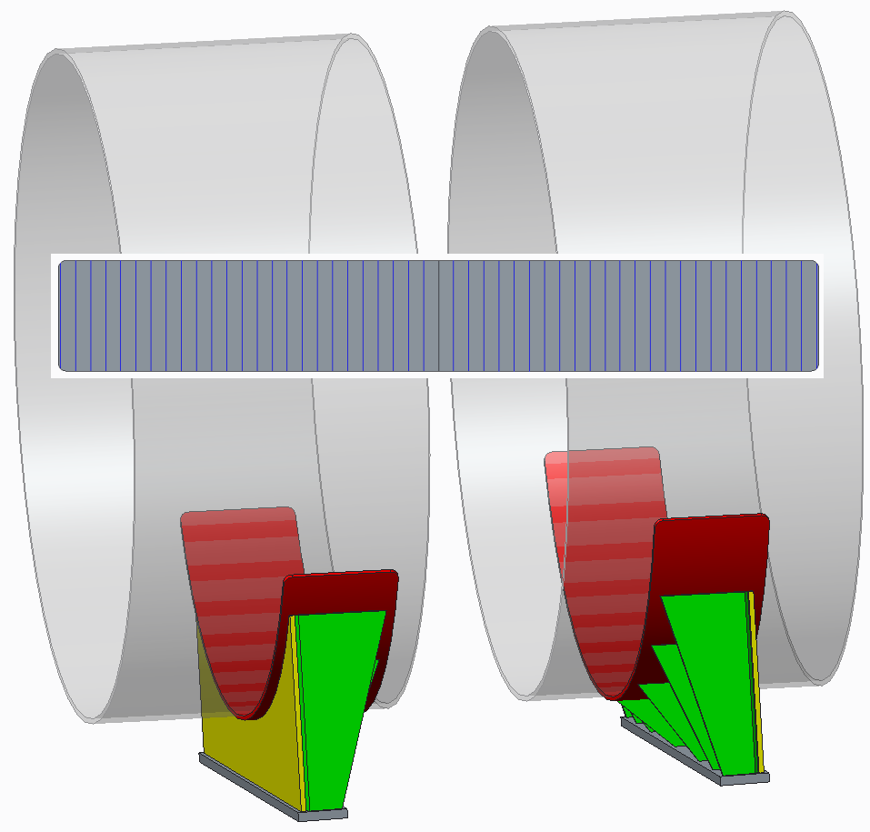
Because I need many markings on the saddle plate (the RED plate in the screenshots below), I tried to draw the lines (=projection of a sketch in the surface of the plate) on 1 side of the saddle plate, group all these projections, and then mirror this group.
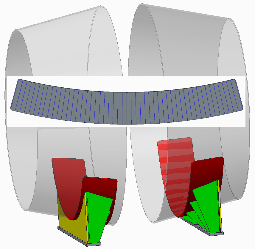
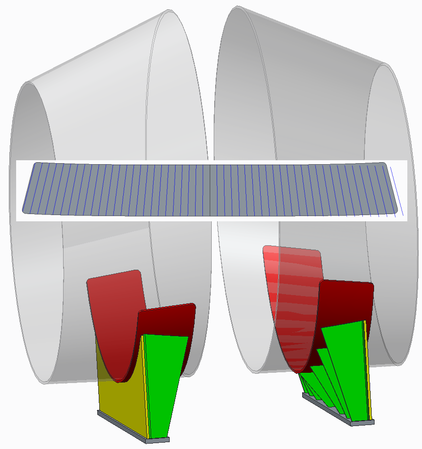
I drew the lines on the left side of the screenshot, the mirror feature mirrors the lines to the right side.
It seemed everything went fine in the beginning.
Example for a cylindrical shell: (screenshot of the flat state pasted on top of the drawing)
Example for a conical shell: (screenshot of the flat state pasted on top of the drawing)
Example for an eccentric conical shell: (screenshot of the flat state pasted on top of the drawing)
As you can see, the mirror feature for the cylindrical and conical shell works like a charm.
The mirror feature for the eccentric cone is not correct.
Would this be a bug in Creo, or do I use this feature in the wrong way?
This thread is inactive and closed by the PTC Community Management Team. If you would like to provide a reply and re-open this thread, please notify the moderator and reference the thread. You may also use "Start a topic" button to ask a new question. Please be sure to include what version of the PTC product you are using so another community member knowledgeable about your version may be able to assist.
- Labels:
-
Assembly Design
- Mark as New
- Bookmark
- Subscribe
- Mute
- Subscribe to RSS Feed
- Permalink
- Notify Moderator
From a lot of things that I have seen with mirror, you are better off creating separate parts. If you update the original, the mirror does not always update correctly.
- Mark as New
- Bookmark
- Subscribe
- Mute
- Subscribe to RSS Feed
- Permalink
- Notify Moderator
Was this using the save-as mirror? Regardless if it is independent or not? Saved-as individually (parts rather than assembly)? Please explain how the part was mirrored.
Regardless, this is certainly one for the developers to look at.
- Mark as New
- Bookmark
- Subscribe
- Mute
- Subscribe to RSS Feed
- Permalink
- Notify Moderator
Hi,
It isn't a mirrored copy of a part. That we have done for the green ribs. Until now we didn't had any problems concerning that part.
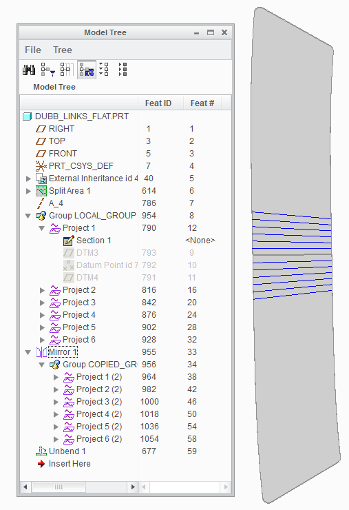
This is a mirror of a feature in a part. This is the tree, not from the complete set of lines. There are up to 72 lines in total needed. It would be very convenient to have to draw 'only' 36 lines, and then mirror them. Especially because every projection needs 2 datumplanes and 2 datumpoints and a sketch to create.
- Mark as New
- Bookmark
- Subscribe
- Mute
- Subscribe to RSS Feed
- Permalink
- Notify Moderator
Okay, I thought the problem was with the geometry. I might suggest that the mirror is working perfectly and that something is slightly askew with your projection method.
As I noted before when making the saddle; datums seem to be dynamic between the bent and unbent stated. Datums created in the flat state "move" in the folder state. I suspect something like this is happening to your part.
Is there a clever way in which you can pattern your projections instead creating each one?
- Mark as New
- Bookmark
- Subscribe
- Mute
- Subscribe to RSS Feed
- Permalink
- Notify Moderator
I've tried several things to use a pattern, but I think it's not possible. There are too many steps to take for each projection.
The projection itself would be much easier if I coul just project the centerline to the surface, but there I get the error that the distance between the sketch and the surface is way to big.
But to get back to the mirror-issue. I tried several things in the mean time, and I did notice something.
- for the cylinder, the mirror is 'easy': it is straight.
- for the cone, the mirror follows the cruvature of the unbent part without a problem.
- for the eccentric cone, the mirror seems to do the right thing, but to the wrong direction.
The flat state of the eccentric cone will always be an U-like shape. But the lines make a ~-like shape. I'll post a close-up in the morning.
- Mark as New
- Bookmark
- Subscribe
- Mute
- Subscribe to RSS Feed
- Permalink
- Notify Moderator
There is a lot going on in the background with sheetmetal. You might just send this to CS anyway just to have them look at it.
Dale is right that mirror seems to have a lot of bugs but nothing will be fixed if they don't investigate. Your application is very logical and should function normally or someone needs to explain why not.
- Mark as New
- Bookmark
- Subscribe
- Mute
- Subscribe to RSS Feed
- Permalink
- Notify Moderator
As promised the screenshot:
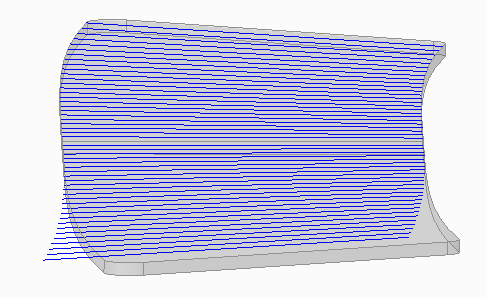
It seems the mirror follows the correct curve, but in the wrong direction.
How do I send this to CS to be investigated?
- Mark as New
- Bookmark
- Subscribe
- Mute
- Subscribe to RSS Feed
- Permalink
- Notify Moderator
Just fill out a form here:
https://www.ptc.com/appserver/cs/case/case_logger.jsp
You will need an SCN #, Service Contract Number which your administrator should be able to provide.


