Community Tip - Visit the PTCooler (the community lounge) to get to know your fellow community members and check out some of Dale's Friday Humor posts! X
- Community
- Creo+ and Creo Parametric
- 3D Part & Assembly Design
- Re: Model to Help 5th Graders Understand PTC Coord...
- Subscribe to RSS Feed
- Mark Topic as New
- Mark Topic as Read
- Float this Topic for Current User
- Bookmark
- Subscribe
- Mute
- Printer Friendly Page
Model to Help 5th Graders Understand PTC Coordinate System
- Mark as New
- Bookmark
- Subscribe
- Mute
- Subscribe to RSS Feed
- Permalink
- Notify Moderator
Model to Help 5th Graders Understand PTC Coordinate System
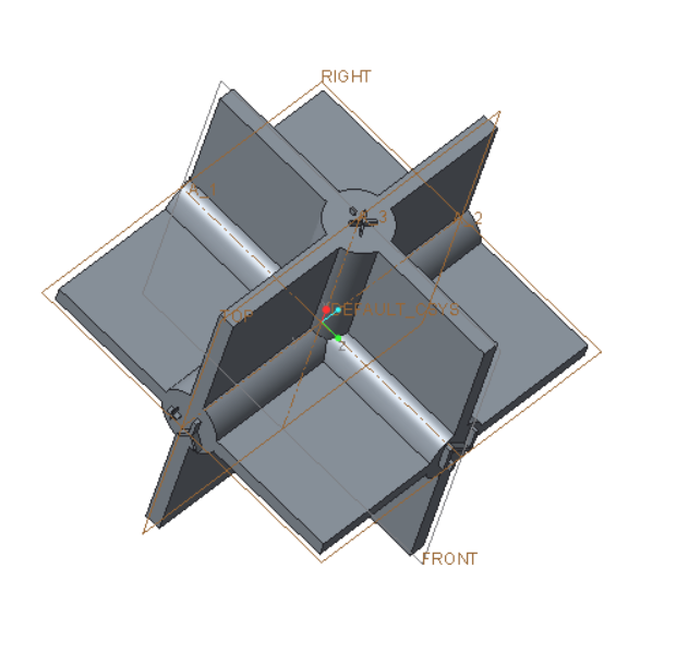
I've made the following model with which I hope to explain the PTC coordinate system to 5th Graders. I've succeeded only in confusing myself. Maybe you can help.

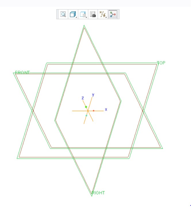
The file is attached. Created with Creo Parametric 3.0 M070 Academic. I think this a right hand system as pictured, I've extruded X+, X-. Y+, Y-, Z+ and Z-. I want to extrude (20mm) FRONT+, FRONT-, TOP+, TOP-, RIGHT+ and RIGHT_ on the planes I presume that FRONT+ is on the Y+ side of the FRONT plane. Am I on the right track?
It seems to me that the default system in Creo Academic is a left handed system!!!
This thread is inactive and closed by the PTC Community Management Team. If you would like to provide a reply and re-open this thread, please notify the moderator and reference the thread. You may also use "Start a topic" button to ask a new question. Please be sure to include what version of the PTC product you are using so another community member knowledgeable about your version may be able to assist.
- Labels:
-
General
- Mark as New
- Bookmark
- Subscribe
- Mute
- Subscribe to RSS Feed
- Permalink
- Notify Moderator
Fortunately you can do a lot in Creo Academic without understanding the Right, Left etc nomenclature.
I'm trying to learn Creo using

This is not appropriate for 5th graders. Chapter 5 entitled "Datum" is almost unreadable. It does give you some insight on how to edit.
On Day 1 I intend to teach how Creo toggles back and forth from 2D to 3D. You never really leave 3D. In the 2D case you look straight down some axis so it looks like 2D.
It would be nice if the planes were labelled XYZ plus or minus.
Front XZ+
Back XZ-
Top XY+
Bottom XY-
Right YZ+
Left YZ-

Whether I should teach 5th graders to work with user defined coordinates rather than Creo default is a good question. I'll have to think about it. At some point I need to discuss the historical reason for PTC coordinates.
First they need to know about the right hand rule and orthogonality.

Maybe Day 365
- Mark as New
- Bookmark
- Subscribe
- Mute
- Subscribe to RSS Feed
- Permalink
- Notify Moderator
Hi,
it seems to me that datum plane names are only text strings. User can set naming convention according his needs. Also view names are only text strings and user can interpret them according his needs. Terms as Front, Top, etc. are understandable when doing model reorientation.

- model surface selected as Front reference will be oriented parallel to display screen with its normal pointing "to the user"
- model surface selected as Back reference will be oriented parallel to display screen with its normal pointing "away from the user"
- model surface selected as Top reference will be oriented perpendicularly to display screen with its normal pointing "up"
- model surface selected as Bottom reference will be oriented perpendicularly to display screen with its normal pointing "down"
- model surface selected as Left reference will be oriented perpendicularly to display screen with its normal pointing "leftwards"
- model surface selected as Right reference will be oriented perpendicularly to display screen with its normal pointing "rightwards"
MH
Martin Hanák
- Mark as New
- Bookmark
- Subscribe
- Mute
- Subscribe to RSS Feed
- Permalink
- Notify Moderator
Well, that's the default coordinate system for the academic version.
Funny how the default spin center symbol did not follow along. Oversight by PTC?
In the commercial version, the center and the default coordinate system do agree.
- « Previous
-
- 1
- 2
- Next »


