Community Tip - Learn all about PTC Community Badges. Engage with PTC and see how many you can earn! X
- Community
- Creo+ and Creo Parametric
- 3D Part & Assembly Design
- Multiple chamfers on drawings
- Subscribe to RSS Feed
- Mark Topic as New
- Mark Topic as Read
- Float this Topic for Current User
- Bookmark
- Subscribe
- Mute
- Printer Friendly Page
Multiple chamfers on drawings
- Mark as New
- Bookmark
- Subscribe
- Mute
- Subscribe to RSS Feed
- Permalink
- Notify Moderator
Multiple chamfers on drawings
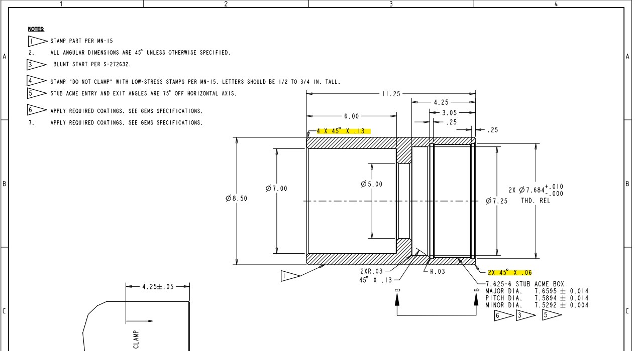
I have a question about the grouping of items like chamfers on a drawing. Take the below for example:

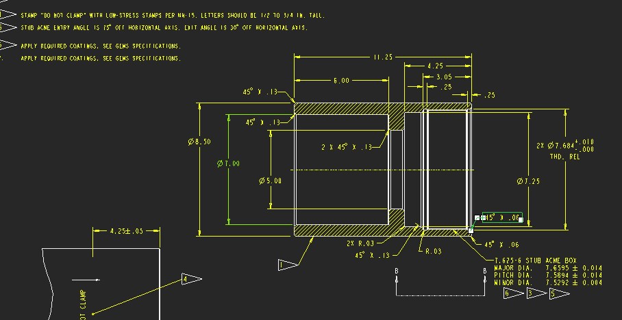
See I had always thought it was fine to group items like this only if on the same feature. say if the O.D had a chamfer at either end then 2X would be acceptable. I have the drawing changed below but I wonder if(especially with more complex drawings) this can get a little busy looking. Is there a middle ground where common sense just comes into play?

Trivial thing but any thoughts appreciated.
This thread is inactive and closed by the PTC Community Management Team. If you would like to provide a reply and re-open this thread, please notify the moderator and reference the thread. You may also use "Start a topic" button to ask a new question. Please be sure to include what version of the PTC product you are using so another community member knowledgeable about your version may be able to assist.
Solved! Go to Solution.
- Labels:
-
General
Accepted Solutions
- Mark as New
- Bookmark
- Subscribe
- Mute
- Subscribe to RSS Feed
- Permalink
- Notify Moderator
I would have to agree that the end result is to have a drawing that is easily understood. Too many dimensions clutter a drawing. Grouping dimensions cuts down on the clutter but can lead to some ambiguity. The original can be understood, but requires studying the drawing and counting chamfers. On the new version I would combine the two .13 chamfers on the end.
Look at it as though you have never seen it before or ask someone else to look at it. If there is head scratching or delay while trying to interpret the drawing, it should be made clearer.
There is always more to learn in Creo.
- Mark as New
- Bookmark
- Subscribe
- Mute
- Subscribe to RSS Feed
- Permalink
- Notify Moderator
IMHO it comes down to the most fundamental rule of drawings: they should be clear and unambiguous to understand.
If you have multiples of .06 and .13 chamfers, is the drawing at a scale where they can be easily distinguished? If 2x is specified, is there more than one position which could be the second chamfer? For instance, if you say "2x 45°x.06" on an external (OD) edge, the 'other' chamfer of that set could be either the internal (ID) edge, or the external edge on the other end of the cylinder. If that other external edge is dimensioned "2x 45°x.13", then it's probably safe to assume the it's the ID and OD edges on the same end that are referred to by the "2x". In other cases, I might instead use "45°x.06 BOTH ENDS"...
If there are eight chamfers on the part in total, and two of them are individually labelled (or form an obvious pair using "2x") then it's probably fine to dimension the rest (assuming they're all the same!) as "6x ...".
If in doubt, perhaps give the drawing to a colleague and ask them which chamfers they think each "2x" and "4x" refers to!
- Mark as New
- Bookmark
- Subscribe
- Mute
- Subscribe to RSS Feed
- Permalink
- Notify Moderator
Another option is to use multiple leader lines to the 2 chamfers on each end of the part to save space with only 1 line of text.
As long as the drawing can be read without misinterpreted dimensions, then it should be fine.
- Mark as New
- Bookmark
- Subscribe
- Mute
- Subscribe to RSS Feed
- Permalink
- Notify Moderator
I would have to agree that the end result is to have a drawing that is easily understood. Too many dimensions clutter a drawing. Grouping dimensions cuts down on the clutter but can lead to some ambiguity. The original can be understood, but requires studying the drawing and counting chamfers. On the new version I would combine the two .13 chamfers on the end.
Look at it as though you have never seen it before or ask someone else to look at it. If there is head scratching or delay while trying to interpret the drawing, it should be made clearer.
There is always more to learn in Creo.
- Mark as New
- Bookmark
- Subscribe
- Mute
- Subscribe to RSS Feed
- Permalink
- Notify Moderator
Daryl,
As drawing standards can vary drastically between companies, this sort of thing may vary. If you have someone in charge of your drafting standards, that would be the best source. After that, as everyone else has stated: do whatever makes the drawing easy to understand.
And, for anyone who is interested, as far as ASME Y14.5-2009 is concerned on page 22 (section 1.9.5 Repetitive Features or Dimensions), "Repetitive features...may be specified by the use of an X...with a numeral to indicate the 'number of places'..." (I know, a lot of ellipses; the statement is way too wordy for a brief quote otherwise) It then goes on to explain spacing of characters for legibility.


