
Turn on suggestions
Auto-suggest helps you quickly narrow down your search results by suggesting possible matches as you type.
Showing results for
Please log in to access translation
Turn on suggestions
Auto-suggest helps you quickly narrow down your search results by suggesting possible matches as you type.
Showing results for
Community Tip - Learn all about the Community Ranking System, a fun gamification element of the PTC Community. X
- Community
- Creo+ and Creo Parametric
- 3D Part & Assembly Design
- New GD&T Profile Tolerance
Translate the entire conversation x
Please log in to access translation
Options
- Subscribe to RSS Feed
- Mark Topic as New
- Mark Topic as Read
- Float this Topic for Current User
- Bookmark
- Subscribe
- Mute
- Printer Friendly Page
New GD&T Profile Tolerance
Apr 02, 2014
02:57 PM
- Mark as New
- Bookmark
- Subscribe
- Mute
- Subscribe to RSS Feed
- Permalink
- Notify Moderator
Please log in to access translation
Apr 02, 2014
02:57 PM
New GD&T Profile Tolerance
[cid:image001.png@01CF4E79.95116BF0]
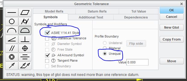
A new symbol, circle U, was added to profile tolerance. In the past, a design engineer wanting to specify an unequal profile tolerance on the drawing would draw a chain line in the applicable area. Two arrows were shown to displace the tolerance zone. In the new standard, the circle U symbol follows the toleranced value in the profile feature-control frame. This announces that an unequal tolerance is in effect.
Is there some way to add this to the interface?
[cid:image003.png@01CF4E83.87B03C70]
Regards,
[cid:012445618@15012007-1FE4]
This thread is inactive and closed by the PTC Community Management Team. If you would like to provide a reply and re-open this thread, please notify the moderator and reference the thread. You may also use "Start a topic" button to ask a new question. Please be sure to include what version of the PTC product you are using so another community member knowledgeable about your version may be able to assist.
Labels:
- Labels:
-
Sheet Metal Design
4 REPLIES 4
Apr 02, 2014
03:51 PM
- Mark as New
- Bookmark
- Subscribe
- Mute
- Subscribe to RSS Feed
- Permalink
- Notify Moderator
Please log in to access translation
Apr 02, 2014
03:51 PM
It's almost 5 years since ASME added the (U) symbol and almost 10 year since it was first proposed. If it's not there now...
Besides, the chain line is more direct.
x
Apr 02, 2014
04:46 PM
- Mark as New
- Bookmark
- Subscribe
- Mute
- Subscribe to RSS Feed
- Permalink
- Notify Moderator
Please log in to access translation
Apr 02, 2014
04:46 PM
A circle U is used in ASME, ASME Y14.41-2003 to be exact.It refers to the distance from the surface a profile tolerance is offset. A distance of 0.000 means that the tolerance is bilateral.This does away with having to draw a phantom line to denote which side a profile tolerance is applied to.
If its not a standard in the ProE drawing call out make a symbol
From: -
To: -
Subject: [proecad] - New GD&T Profile Tolerance
Date: Wed, 2 Apr 2014 18:57:10 +0000
A new symbol,
circle U, was added to profile tolerance. In the past, a design
engineer wanting to specify an unequal profile tolerance on the drawing would draw a chain line in the applicable area. Two arrows were shown to displace the tolerance zone. In the new standard, the circle U symbol follows the toleranced value in the profile
feature-control frame. This announces that an unequal tolerance is in effect.
Is there some way to add this to the interface?
Regards,
Robert Altman
Manager, CAD Engineering & Tech Support
Apr 02, 2014
05:51 PM
- Mark as New
- Bookmark
- Subscribe
- Mute
- Subscribe to RSS Feed
- Permalink
- Notify Moderator
Please log in to access translation
Apr 02, 2014
05:51 PM
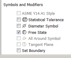
You can turn this on in the drawing options.
ASME Y14.41
Circle U and other ASME Y14.41 settings
File-> Prepare-> Drawing Properties ->Detail Options
[cid:image004.jpg@01CF4E83.014CB3C0]
[cid:image005.png@01CF4E83.014CB3C0]
[cid:image001.png@01CE8938.2DDEC0B0]
Chad Smith
Product Engineer | Upper Extremity
www.acumed.net
ASME Y14.41
Circle U and other ASME Y14.41 settings
File-> Prepare-> Drawing Properties ->Detail Options
[cid:image004.jpg@01CF4E83.014CB3C0]
[cid:image005.png@01CF4E83.014CB3C0]
[cid:image001.png@01CE8938.2DDEC0B0]
Chad Smith
Product Engineer | Upper Extremity
www.acumed.net
Apr 02, 2014
06:41 PM
- Mark as New
- Bookmark
- Subscribe
- Mute
- Subscribe to RSS Feed
- Permalink
- Notify Moderator
Please log in to access translation
Apr 02, 2014
06:41 PM
Ahh, Creo or Creo 2
x


