
Turn on suggestions
Auto-suggest helps you quickly narrow down your search results by suggesting possible matches as you type.
Showing results for
Please log in to access translation
Turn on suggestions
Auto-suggest helps you quickly narrow down your search results by suggesting possible matches as you type.
Showing results for
Community Tip - Learn all about the Community Ranking System, a fun gamification element of the PTC Community. X
- Community
- Creo+ and Creo Parametric
- 3D Part & Assembly Design
- Re: Protrusion circular pattern fails to fill 360 ...
Translate the entire conversation x
Please log in to access translation
Options
- Subscribe to RSS Feed
- Mark Topic as New
- Mark Topic as Read
- Float this Topic for Current User
- Bookmark
- Subscribe
- Mute
- Printer Friendly Page
Protrusion circular pattern fails to fill 360 degrees
Sep 16, 2022
07:18 AM
- Mark as New
- Bookmark
- Subscribe
- Mute
- Subscribe to RSS Feed
- Permalink
- Notify Moderator
Please log in to access translation
Sep 16, 2022
07:18 AM
Protrusion circular pattern fails to fill 360 degrees
Hi,
I am having a problem creating a circular pattern of a protrusion in Creo 4.0 .
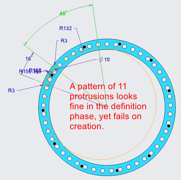
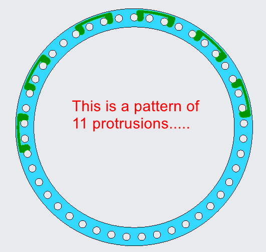
The pattern should distribute evenly around a 360 degrees circle, yet it only fills up half of the circle. Some of the protrusions seem to overlap or just fail.
I am having this problem since day one of using Pro/E and Creo. Sometimes it works, sometimes not. I must be doing something wrong. Not sure what.
I tried 2 different ways.
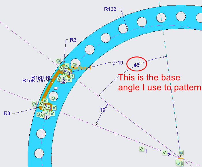
- A dimensional pattern on the base angle of the protrusion
- A reference pattern of the protrusion, by first patterning the reference datum plane of the protrusion.
Both ways fail.
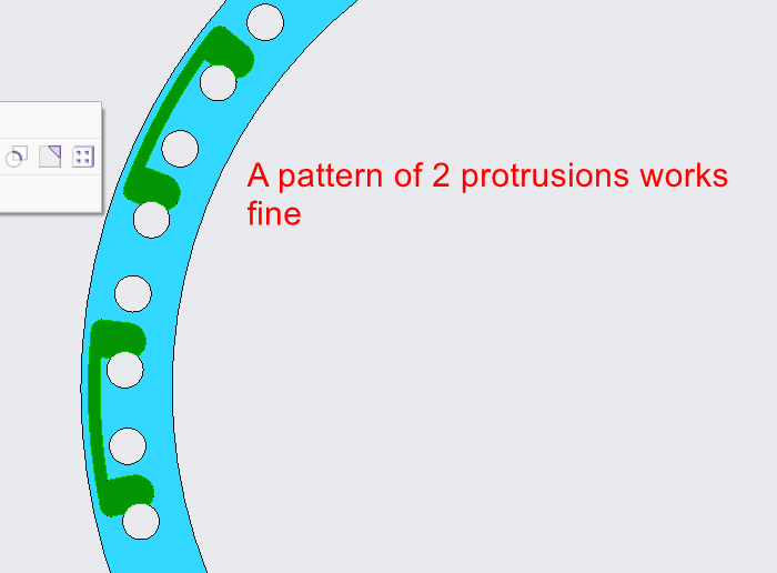
The pattern works, as long as the total angle used is less than 180 degrees. When trying to fill the full 360 degrees, the protrusions overlap or fail.
Screenshots are hopefully helpful to understand the problem.
Solved! Go to Solution.
Labels:
- Labels:
-
General
- Tags:
- patterning
ACCEPTED SOLUTION
Accepted Solutions
Sep 16, 2022
07:50 AM
- Mark as New
- Bookmark
- Subscribe
- Mute
- Subscribe to RSS Feed
- Permalink
- Notify Moderator
Please log in to access translation
Sep 16, 2022
07:50 AM
Your issue is caused by how Creo splits circles into halves. I would suggest using an axial pattern for this geometry. Creo 7 example model enclosed for reference. In this example a sketched point with a clocking angle is used to set up the pattern. This is not the only way to do it but is easy and stable.

========================================
Involute Development, LLC
Consulting Engineers
Specialists in Creo Parametric
Involute Development, LLC
Consulting Engineers
Specialists in Creo Parametric
4 REPLIES 4
Sep 16, 2022
07:44 AM
- Mark as New
- Bookmark
- Subscribe
- Mute
- Subscribe to RSS Feed
- Permalink
- Notify Moderator
Please log in to access translation
Sep 16, 2022
07:44 AM
I've never had any luck, in the years and years I've used Pro/ENGINEER and then Creo, with dimensional circular patterns. Overlaps and duplications seem to be unavoidable with, as you state, anything over 180 degrees. What has worked for us is patterns based upon an axis. Those seem to, for some mysterious reason, work correctly. The underlying calculation algorithm must be newer and thus perhaps better. It does require that you have an axis at the center of your part, but 9 times out of 10 that's already happened as a result of the base model construction.
Hopefully this will help and is amenable to your modeling needs.
Sep 16, 2022
07:50 AM
- Mark as New
- Bookmark
- Subscribe
- Mute
- Subscribe to RSS Feed
- Permalink
- Notify Moderator
Please log in to access translation
Sep 16, 2022
07:50 AM
Your issue is caused by how Creo splits circles into halves. I would suggest using an axial pattern for this geometry. Creo 7 example model enclosed for reference. In this example a sketched point with a clocking angle is used to set up the pattern. This is not the only way to do it but is easy and stable.
========================================
Involute Development, LLC
Consulting Engineers
Specialists in Creo Parametric
Involute Development, LLC
Consulting Engineers
Specialists in Creo Parametric
Sep 16, 2022
08:21 AM
- Mark as New
- Bookmark
- Subscribe
- Mute
- Subscribe to RSS Feed
- Permalink
- Notify Moderator
Please log in to access translation
Sep 16, 2022
08:21 AM
Hi,
to get 360 degree dimension pattern you have to apply very old trick - create datum plane on the fly.
I uploaded video and part.
Martin Hanák
Sep 16, 2022
08:34 AM
- Mark as New
- Bookmark
- Subscribe
- Mute
- Subscribe to RSS Feed
- Permalink
- Notify Moderator
Please log in to access translation
Sep 16, 2022
08:34 AM
Now that you mention it, I remember using that method in the past. I somehow forgot to apply it here.
Thank you!
The method, as suggested by @tbraxton and @KenFarley above also works. That is, not to use a reference or dimensional pattern, but an Axis pattern.
Great! Thank you all so much for providing me with not one, but two solutions for this problem which has caused me so much frustration in the past!


