Community Tip - You can change your system assigned username to something more personal in your community settings. X
- Community
- Creo+ and Creo Parametric
- 3D Part & Assembly Design
- Re: Rectangular helical sweep feature
- Subscribe to RSS Feed
- Mark Topic as New
- Mark Topic as Read
- Float this Topic for Current User
- Bookmark
- Subscribe
- Mute
- Printer Friendly Page
Rectangular helical sweep feature
- Mark as New
- Bookmark
- Subscribe
- Mute
- Subscribe to RSS Feed
- Permalink
- Notify Moderator
Rectangular helical sweep feature
Hello out there,
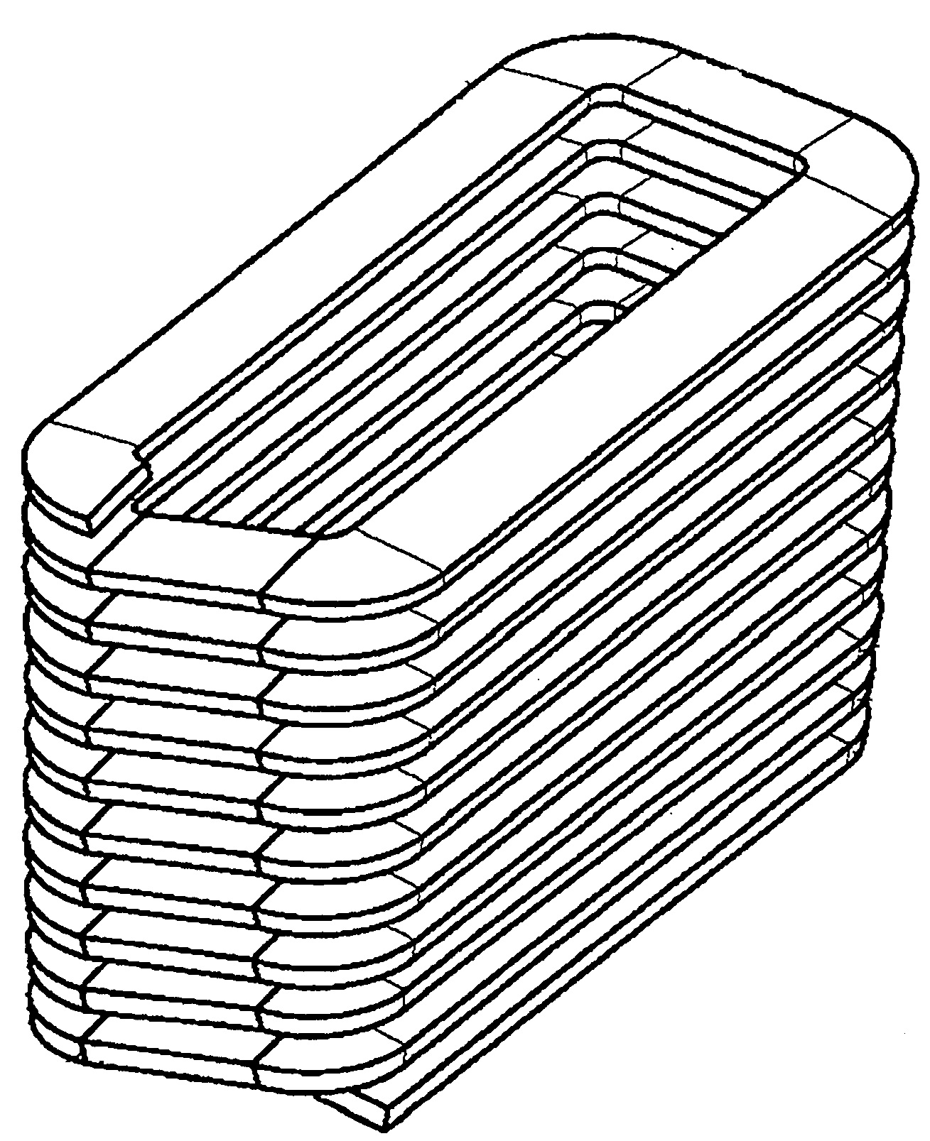
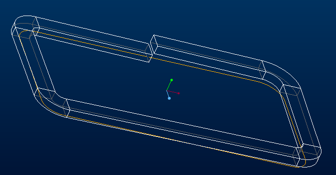
is there anybody out there who knows how to create a rectangular helical sweep Feature, as in the shown black and white Picture?
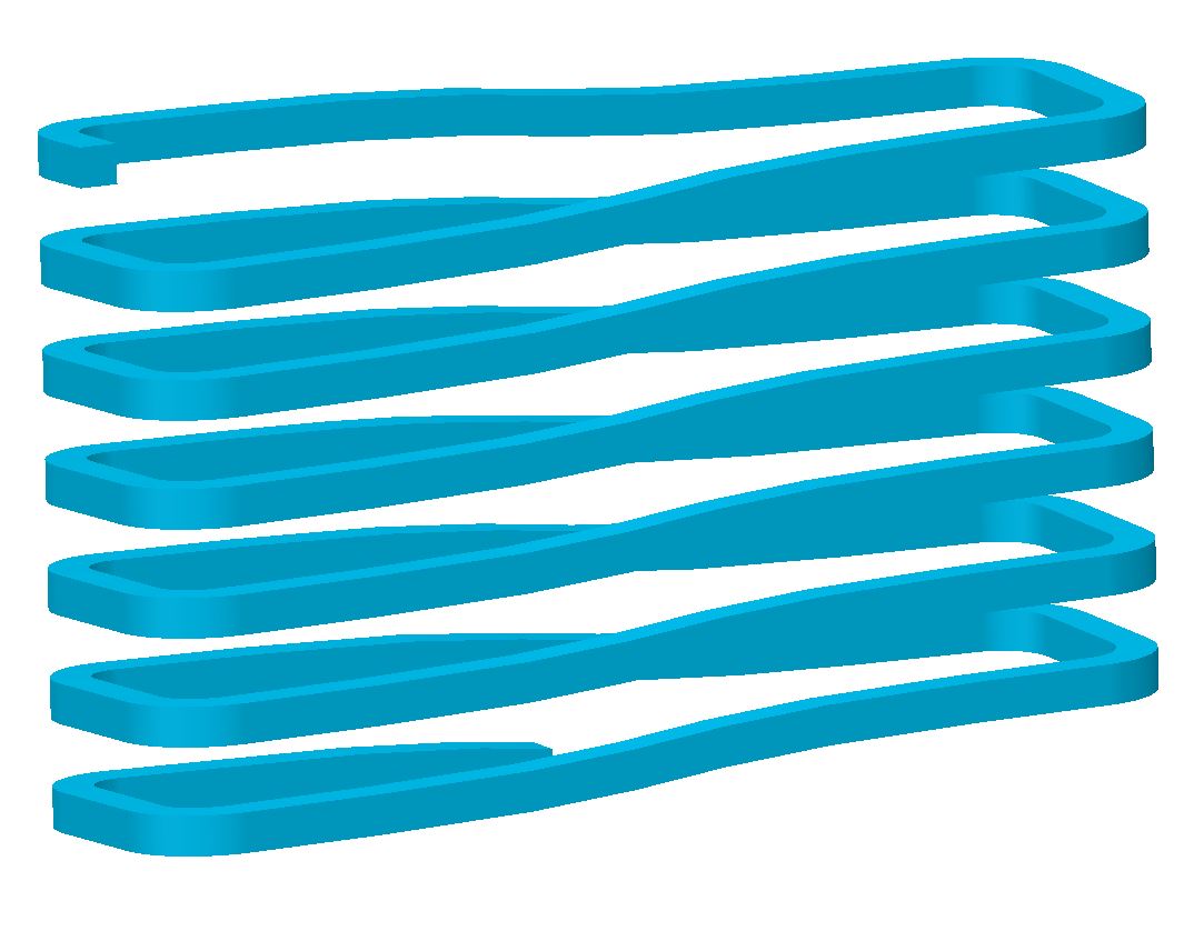
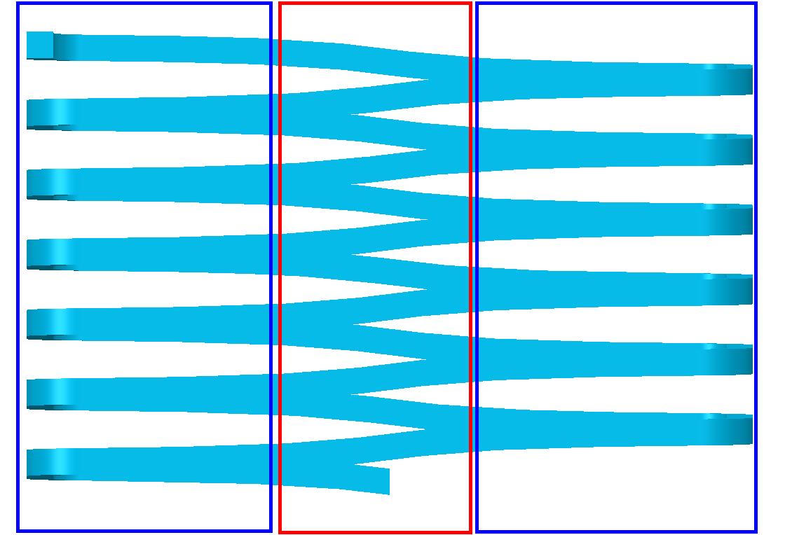
I tried my best to get a solution, but it is not to be used. The gradient is somehow not constant in the red area to the blue area. The reason is the great difference between the inner radius and the outer radius. If the shape of the required rectangle increases, or edge lengths are the same length (quadrangle). Then the slope becomes more linear.
Is there any help out there?
Thanks Heiko
- Labels:
-
General
- Mark as New
- Bookmark
- Subscribe
- Mute
- Subscribe to RSS Feed
- Permalink
- Notify Moderator
How about using the wrapped sketch, like this:
 +
+
- Mark as New
- Bookmark
- Subscribe
- Mute
- Subscribe to RSS Feed
- Permalink
- Notify Moderator
Thank you for your also interesting solution (wrapped sketch) about my question.
Other views are always interesting.
- But what I miss however is the possibility to specify the slope.
- In addition, I find it not good that the Spin Center is no longer in the actual body center. This is beddened by the very long curve.
But again, thanks for your idea.
That's why I did a little Research to get a good solution. And here I need help again to have a solution ready for posterity.
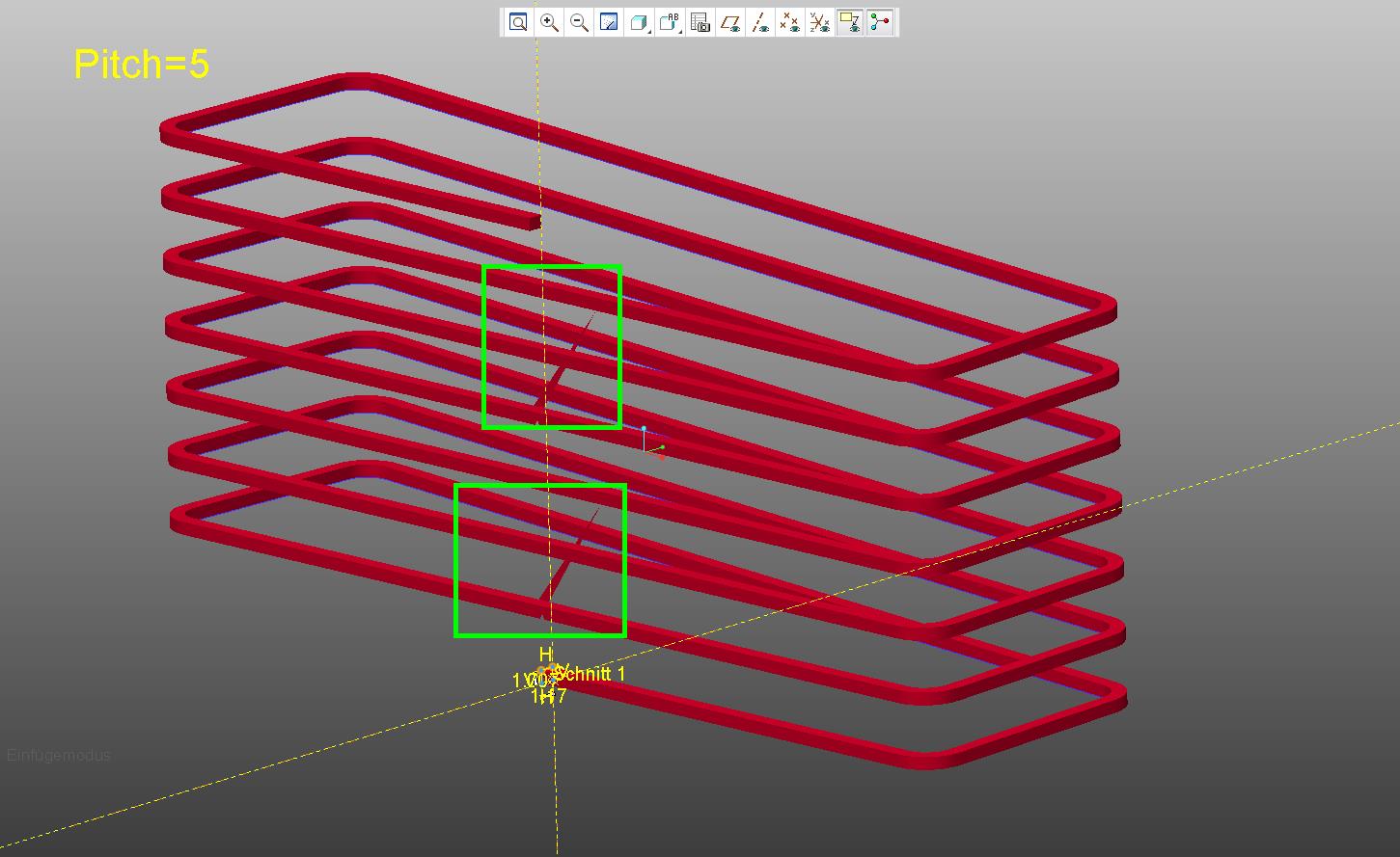
Here I compiled a graph with an offset curve and a pattern. So far so good, .... it works mostly but not constant.
The curve in combination with the graph works very well. The Problem is the sweep Construction element.
Sometimes it works and sometimes not. If you change the profil in the sketcher or the pitch. Then the sweep fails
Could you have a look (or somebody else) on this, maybe you know why and what i did wrong about this Position??
Thanks in advance.
- Mark as New
- Bookmark
- Subscribe
- Mute
- Subscribe to RSS Feed
- Permalink
- Notify Moderator
Unfortunately, I did a quick test and the wrap method will produce a consistent sweep.
Honestly, I'm not surprised that a sweep based on patterning copy-geometry type of features fails inconsistently. I attribute this to poor numerical-error handling deep in the software.
Your first concern about not being able to specify the pitch can be addressed with some relations. Note that the sketch to be wrapped is a simple line that starts at origin and ends at coordinates x,y.
So x = (number of wraps)*("perimeter" of the surface being wrapped)
and y = (number of wraps)*(pitch)
You get this perimeter by saving a length analysis.
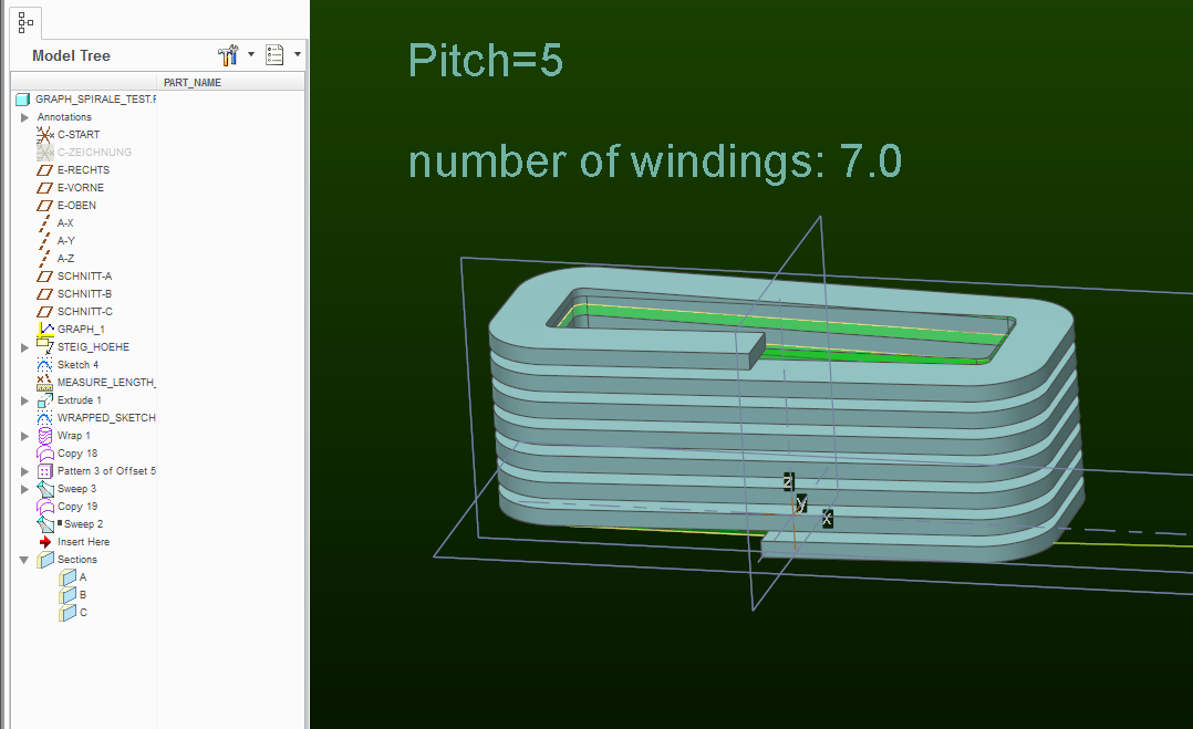
But I completely see your concern about how the sketch that needs to be wrapped around the surface throws off the spin-center of the model.
It is a very frustrating aspect of modeling and drawing in Creo software, because blanking such "construction" entities has no effect.
- Mark as New
- Bookmark
- Subscribe
- Mute
- Subscribe to RSS Feed
- Permalink
- Notify Moderator
Paul Sobejko wrote:
Unfortunately, I did a quick test and the wrap method will produce a consistent sweep.
Honestly, I'm not surprised that a sweep based on patterning copy-geometry type of features fails inconsistently. I attribute this to poor numerical-error handling deep in the software. ...snip
There is a bug in early Creo 2 that fails at the seams of the sweep. It goes normal at the "edge" of the cylinder rather than continuing tangent to the next wrap.
I learned this on doing a single sweep feature spring where every coil had a glitch at this seam.
It has since been reported fixed, but this was a fairly dumb bug as far as bugs go.
The real take-away, however, is other things we learned about continuous curves. For one, they cannot make sharp corners, and they are very sensitive to accuracy settings.
One way to manage the asymmetry of the part is to assign the size of the datum planes.
- Mark as New
- Bookmark
- Subscribe
- Mute
- Subscribe to RSS Feed
- Permalink
- Notify Moderator
Try changing your accuracy value. It appears to have issues at the rounded corners. If you get it to regenerate try changing the width of the section. I tried values of .001 and 15 for accuracy and width respectively and it allowed the feature to regenerate and showed geometry problems at the radii.
- Mark as New
- Bookmark
- Subscribe
- Mute
- Subscribe to RSS Feed
- Permalink
- Notify Moderator
Hello Heiko Hagedorn
see following video tutorial, maybe it can help:
Blog - Creo Tutorials | 4K Side
Regards
- Mark as New
- Bookmark
- Subscribe
- Mute
- Subscribe to RSS Feed
- Permalink
- Notify Moderator
thanks for your answer, it is also a nice version to get a helical sweep.
But does not solve my Problem, ..... unfortunately.
Your solution (YouTube Video) to get a helical sweep, is similar to the Feature "Helical sweep" under the Sweep Button.
There i get a very strange 3D curve, see in the first posting and with the YouTube solution:
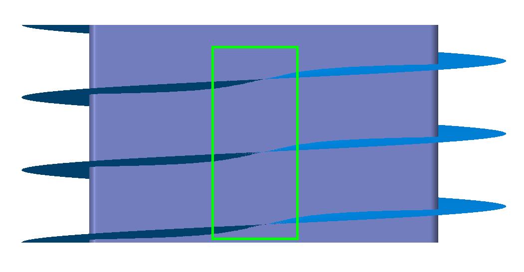
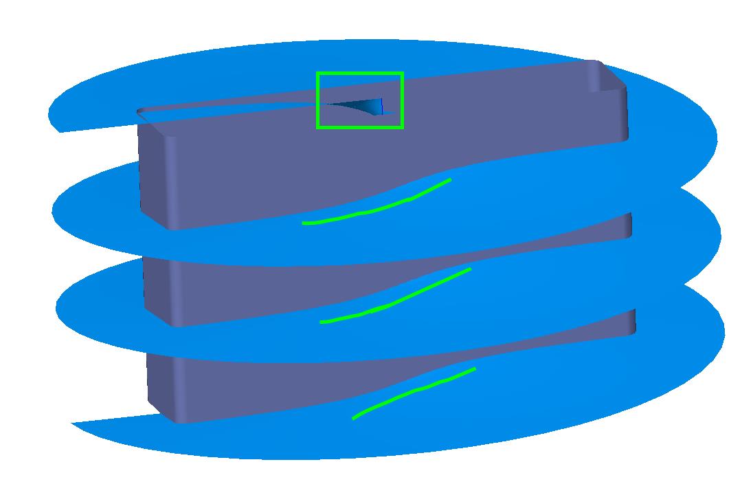
The 3D curve isn't the Problem, this works with my "graph" solution very well. It is only the sweep who makes problems and isn't very stable.
sooooo it means, .... is there still any help out there?
- Mark as New
- Bookmark
- Subscribe
- Mute
- Subscribe to RSS Feed
- Permalink
- Notify Moderator
Your black and white picture is not a helical sweep. It is a series of horizontal segments with a sloped step. This would better be done by creating the sloped step, then a related horizontal segment and then patterning the sloped step and ref-patterning the horizontal segment.
- Mark as New
- Bookmark
- Subscribe
- Mute
- Subscribe to RSS Feed
- Permalink
- Notify Moderator
Glad someone noticed. Make one revolution using evalgraph, then pattern. Done.
- Mark as New
- Bookmark
- Subscribe
- Mute
- Subscribe to RSS Feed
- Permalink
- Notify Moderator
sorry for the late reply and thank you for your comment.
Could you give me more Information about using the evalgraph?
Maybe could you create a fast creo model?
Regards Heiko
- Mark as New
- Bookmark
- Subscribe
- Mute
- Subscribe to RSS Feed
- Permalink
- Notify Moderator
Evalgraph has been covered in depth here in the community.
The idea behind it is to draw an X-Y graph where X is your origin (path zero to one) and Y is the value at that location on the path.
Your graph will look like a stair-step.
- Mark as New
- Bookmark
- Subscribe
- Mute
- Subscribe to RSS Feed
- Permalink
- Notify Moderator
Attached is an example of how to do this using evalgraph. After you have setup a graph, you setup the relation in the section for the sweep. I have also set a relation at the part level to set the pattern distance to equal the value set by the graph.
- Mark as New
- Bookmark
- Subscribe
- Mute
- Subscribe to RSS Feed
- Permalink
- Notify Moderator
Hello to all,
first of all thanks for all that help here!!!! Even there is still no perfect solution yet.
Antonius Dirriwachter thanks for your explanation about how is a evalgraph working.
I think I have understood the function with the evalgraph and the trajpar. As far as I can tell. "I'm still a rookie about this"
, I tried to understand the example what you have attached. So far so good. But your example has one serious error.
The slope consists of 2 Sweep's and not one. AND the blue Sweep is completely flat along the curve. Only the green sweep has the slope.
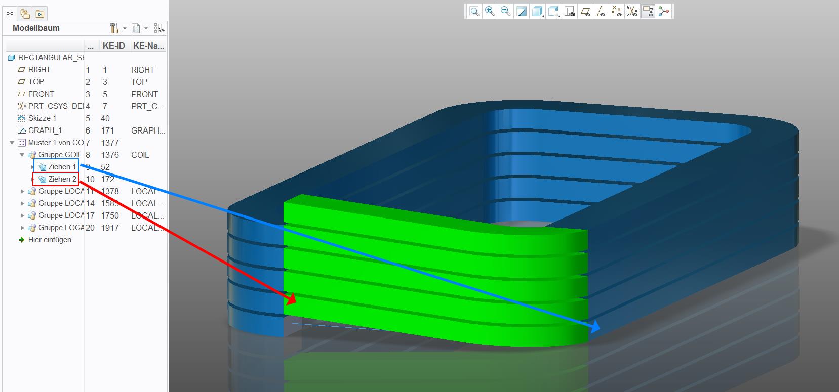
After this diagnosis I tried to use one curve (Skizze 1) where the profile is pulled along. But this only works when the start and end of the curve have a minimum distance.
However, this is technically wrong. It must be closed and only separated in one place.In order for the following curve (patterned) to be combined with the original curve. And no intermediate piece has to be patched.
>> However, if the curve is closed and only separated at one point, the sweep will fail. << I'm getting confused.
Still waiting for a good solution.
- Mark as New
- Bookmark
- Subscribe
- Mute
- Subscribe to RSS Feed
- Permalink
- Notify Moderator
Correct, I set it up as 2 sweeps, a flat section and a sloped section, as is shown in the black and white image you attached. If you're trying to do it as a constant slope it's the same process. Attached is one with a constant slope.
- Mark as New
- Bookmark
- Subscribe
- Mute
- Subscribe to RSS Feed
- Permalink
- Notify Moderator
I used a normal sweep together with trajpar it should give the required geometry. to my suprrise the sweep feature in Creo 2 doesn't allow closed curves having a trajpar parameter
- Mark as New
- Bookmark
- Subscribe
- Mute
- Subscribe to RSS Feed
- Permalink
- Notify Moderator
The original angles the wide section; and it steps only in one of the two short sections.
This is the reason an evalgraph will work well. It is not a constant rate of "anything" which trajpar can utilize.
However, you can bury the evalgraph in the trajpar statement.
It appears that the angle of the "blade" is constant. Correct me if that is not true.
- Mark as New
- Bookmark
- Subscribe
- Mute
- Subscribe to RSS Feed
- Permalink
- Notify Moderator
you are absolutely correct with your explanation about the angles definitions in the white picture from the first post.
Shame on me, about the white example picture. ![]() It was only a fast screenshot, what should show what I like to have.
It was only a fast screenshot, what should show what I like to have.
And I didn't realize which section (area) has the slope. I thought it is linear or. constant. My mistake, sorry about that.
And yes you are right, the "blade" is constant.
And I want to have a linear or constant slope over the complete sweep Feature.
- Mark as New
- Bookmark
- Subscribe
- Mute
- Subscribe to RSS Feed
- Permalink
- Notify Moderator
Oh, that changes things a lot ![]()
- Mark as New
- Bookmark
- Subscribe
- Mute
- Subscribe to RSS Feed
- Permalink
- Notify Moderator
This is probably another way to model the geometry. It requires more steps but I hope it does give you what you wanted. I apologize if I have misunderstood the intent.
- Mark as New
- Bookmark
- Subscribe
- Mute
- Subscribe to RSS Feed
- Permalink
- Notify Moderator
I am looking at your model and wish to make a couple of comments worth investigating.
This is the right way to do something when you have to know the system does what you expect.
In the end, the analysis tools provided by Creo will bring out a lot of little things that take a moment to understand.
1st comment is that the section needs to be normal to the trajectory is you are forming materials...
which causes an unwanted twist to the geometry normally not noticed on round sections.
This is where that "trust" issue with the system comes in. If it is "analysis critical", then you would have to manage the twist also.
We have done that in other posts, but in short, ...
you create a guide curve for the Sweep feature as a chain (second pick) just to keep your section oriented throughout the sweep.
Also, I am no fan of copy geometry. This one easily patterns. If the sweep was solid, it would all merge automatically too.
- Mark as New
- Bookmark
- Subscribe
- Mute
- Subscribe to RSS Feed
- Permalink
- Notify Moderator
BH OOI Thanks for your idea and a your way to get a solution with normal available on board Tools. Whether it is the right solution, it is a interesting point of view.
Antonius Dirriwachter Your comments about the idea from BH OOI are also very needful. And your are absolutely right with the your comment about the orientation from the sweep. It has to be normal to the trajectory. And you are talking about to manage the following twist.
Either my English is so bad or google translate. That's why I have still not understand the following question:
- How do you get the twist from the curve or the sweep straightened?
Thanks in advance.
- Mark as New
- Bookmark
- Subscribe
- Mute
- Subscribe to RSS Feed
- Permalink
- Notify Moderator
You just make a "parallel" curve to your origin curve.
In you sweep sketch, you can use this Chain reference to orient your sketch.
The attached file won't fail without the additional chain, but you get the idea by interrogating the sweep feature.
- Mark as New
- Bookmark
- Subscribe
- Mute
- Subscribe to RSS Feed
- Permalink
- Notify Moderator
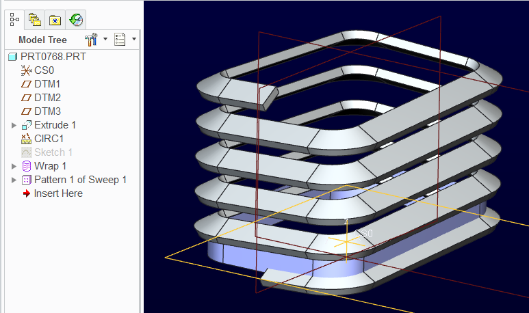
This would be my entry for this challenge.
It utilizes a wrap to manage the constant rise.
This is fairly simple to make parametric for a variety of shapes.
This method also does not require a "guide curve".
P.S. This is also Paul's solution above and with the clarification, I would suggest his answer is correct.
- Mark as New
- Bookmark
- Subscribe
- Mute
- Subscribe to RSS Feed
- Permalink
- Notify Moderator
I like this solution a lot. It's very simple and robust. I could alter the shape of the extrusion section and the wrap works just fine.
However, there is one issue I found. It works fine on the straight extruded surface but not on the tapered surface, as shown below:
May be for tapered surface, we have to deal it differently. Thoughts ?
- Mark as New
- Bookmark
- Subscribe
- Mute
- Subscribe to RSS Feed
- Permalink
- Notify Moderator
![]() too true; the logic doesn't work for cones.
too true; the logic doesn't work for cones.
You should be able to develop the right shape, but it is not straight forward.
Are you remembering to use the coordinate axis in the sketch?
Important element in helping to place the wrap! ![]()
- Mark as New
- Bookmark
- Subscribe
- Mute
- Subscribe to RSS Feed
- Permalink
- Notify Moderator
Well, you can project that curve that was wrapped about the "cylinder", onto its conical version:
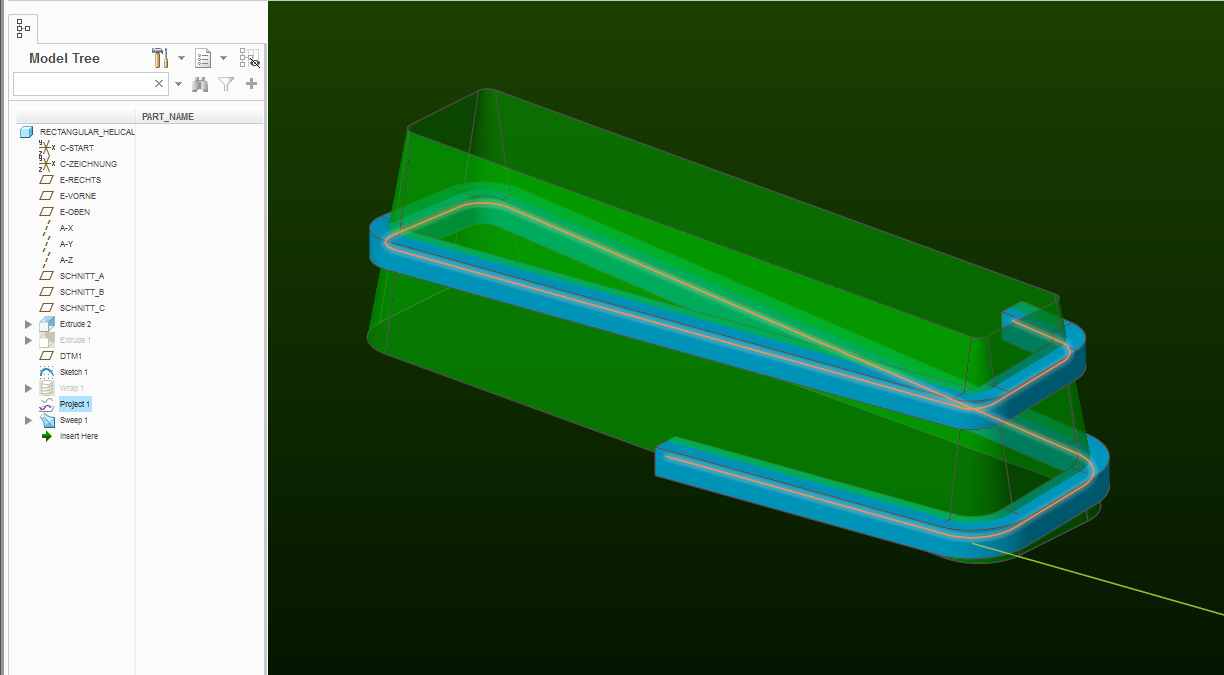
Pictured above is a sweep made using the "normal to projection" section plane control option.
The distortion is easy to observe:
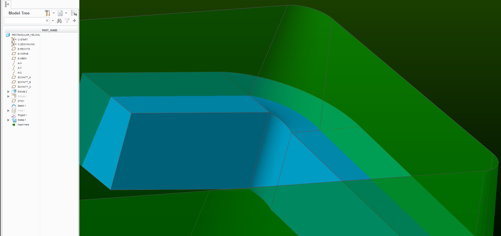
If I reduce the size of the square wire, then you can get the "normal to trajectory" option to work for the sweep:
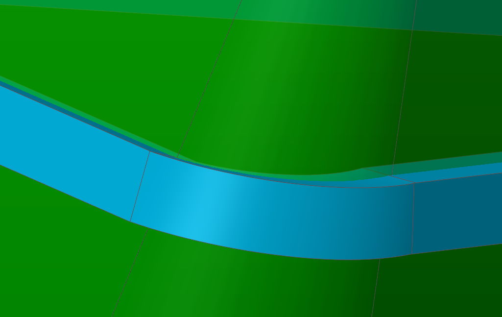
However - similar distortion exists, so I couldn't tell you which is a more realistic model.
- Mark as New
- Bookmark
- Subscribe
- Mute
- Subscribe to RSS Feed
- Permalink
- Notify Moderator
Any solid material would have significant deformation in the corners.
The deformation in Creo changes as you change the center of the section in relation to the sweep path.
You would have to map all 4 corners of the profile to get something more accurate.
That can be stitched together with boundary blend.
- Mark as New
- Bookmark
- Subscribe
- Mute
- Subscribe to RSS Feed
- Permalink
- Notify Moderator
No sheetmetal offerings yet? ![]()
- Mark as New
- Bookmark
- Subscribe
- Mute
- Subscribe to RSS Feed
- Permalink
- Notify Moderator
Oh, if only it were possible. I needed something exactly like this to build a the inlet spiral of a cyclone. It would have been nice to have a flat pattern of that, especially when I was building an PVC hot-formed prototype.


