
Turn on suggestions
Auto-suggest helps you quickly narrow down your search results by suggesting possible matches as you type.
Showing results for
Please log in to access translation
Turn on suggestions
Auto-suggest helps you quickly narrow down your search results by suggesting possible matches as you type.
Showing results for
- Community
- Creo+ and Creo Parametric
- 3D Part & Assembly Design
- Re: SCELETON FROM IMPORTED FILE - RESETTING THE OR...
Translate the entire conversation x
Please log in to access translation
Options
- Subscribe to RSS Feed
- Mark Topic as New
- Mark Topic as Read
- Float this Topic for Current User
- Bookmark
- Subscribe
- Mute
- Printer Friendly Page
SCELETON FROM IMPORTED FILE - RESETTING THE ORIGIN
Feb 28, 2013
05:16 AM
- Mark as New
- Bookmark
- Subscribe
- Mute
- Subscribe to RSS Feed
- Permalink
- Notify Moderator
Please log in to access translation
Feb 28, 2013
05:16 AM
SCELETON FROM IMPORTED FILE - RESETTING THE ORIGIN
Dear all,
I'm busy with a scructure where I use a sceleton that comes from an 'imported wireframe/surface designfile.
I have cleaned up the designfile first, removing all I din't need but putting it on top of my assembly it results that the section of the designfile I use as sceleton is far away from the default coordinate system...
Sceleton parts seem to assemble automatically 'default'? So I can not move it in my assembly...
Replacing the base planes and coordinate system doesnt help, putting it default it is put on the 'old' coordinates...
Working in Creo 2 (not so familiar, came from wildfire 4 or 5) I tried to copy the imported feature and pase special to apply a move to it, but I cant copy...
So in short, how to put the default coordinate and a the coordinate of an 'imported' skeleton part together...
Thanks!
Didriek
This thread is inactive and closed by the PTC Community Management Team. If you would like to provide a reply and re-open this thread, please notify the moderator and reference the thread. You may also use "Start a topic" button to ask a new question. Please be sure to include what version of the PTC product you are using so another community member knowledgeable about your version may be able to assist.
Labels:
- Labels:
-
Assembly Design
9 REPLIES 9
Feb 28, 2013
08:01 AM
- Mark as New
- Bookmark
- Subscribe
- Mute
- Subscribe to RSS Feed
- Permalink
- Notify Moderator
Please log in to access translation
Feb 28, 2013
08:01 AM
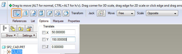
You can use the 'Warp' feature with the 'Transform' option in order to move the geometry relative to the coordinate system.
So effectively you do not move the coordinate system but the result will be the same.
Feb 28, 2013
03:09 PM
- Mark as New
- Bookmark
- Subscribe
- Mute
- Subscribe to RSS Feed
- Permalink
- Notify Moderator
Please log in to access translation
Feb 28, 2013
03:09 PM
It seems that the skeleton file has a random "center". When you assemble it, does it drop in and constrain as "default"? Seems you would want to fix this in the skeleton file so the assembly "default" will be where you want it.
Mar 01, 2013
08:07 AM
- Mark as New
- Bookmark
- Subscribe
- Mute
- Subscribe to RSS Feed
- Permalink
- Notify Moderator
Please log in to access translation
Mar 01, 2013
08:07 AM
Yes, a skeleton is assembled in the Proe / Creo 'default' position where the 3 default planse or default CS are lined up. This si the way it is intended to work, your skeleton's origin and your assembly origin are intended to be the same. In fact, you cannot create a skeleton file outside the contect of the assy, so in a way it's 'orignis' if you will are tied to the assy 'origin'.
I dont' see this as a problem, but you can deal with this simply by buildiung yout skeleton geomtry around the default CS as you desire it to be when assembled in your assy.
Mar 01, 2013
08:12 AM
- Mark as New
- Bookmark
- Subscribe
- Mute
- Subscribe to RSS Feed
- Permalink
- Notify Moderator
Please log in to access translation
Mar 01, 2013
08:12 AM
The way I'd solve this is by aligning specific coordinate systems in your original import. This may take some trial and error and it's best if you have access to the original file and the program which it was created in.
If you can edit the original file in its native program, do so and add a coordinate system where you want the Proe / Creo default CS to be. Then, when importing the file in Proe / Creo choose that CS in the import and the default CS in your skeleton.
Alternatively you need to do the reverse. Determine the offset of the imported data and the Proe/ / Creo CS. Create a new CS in your skeleton offset in the opposite direction. In other words, if your data is offset 1,2,3, you need a CS at -1,-2,-3. Then re-import your data and choose the imported files default CS and this newly created CS in Proe / Creo. That should put your geometry where you want it.
Mar 06, 2013
09:50 AM
- Mark as New
- Bookmark
- Subscribe
- Mute
- Subscribe to RSS Feed
- Permalink
- Notify Moderator
Please log in to access translation
Mar 06, 2013
09:50 AM
Just found a sollution by accident....
The first skeleton you assemble is 'by default', so when your default is not where you want in de imorted geometry you have an issue (this topic)
BUT, the second skeleton you assemble, Creo asks you constrains!
>> what I did is create an new, empty skeleton part A... set as first skeleton (default)
After, I put my 'imorted' skeletons in, by mate/align.... then I fixed them in that position so I can delete the skeleton A
= result, a nice assy whith the imported skeletons where I want them!
Mar 06, 2013
02:47 PM
- Mark as New
- Bookmark
- Subscribe
- Mute
- Subscribe to RSS Feed
- Permalink
- Notify Moderator
Please log in to access translation
Mar 06, 2013
02:47 PM
If it is a simple case of constrains, you should be able to delete the default constraint and then apply a different constraint to the 1st part. My assemblies don't do this any more but I remember when this was the default behavior.
Mar 07, 2013
04:04 AM
- Mark as New
- Bookmark
- Subscribe
- Mute
- Subscribe to RSS Feed
- Permalink
- Notify Moderator
Please log in to access translation
Mar 07, 2013
04:04 AM
With your first skeleton the 'constain' menu is skipped, and I didn't find an edit definition en edit references option...
What I found assebmbling a second skeleton, could be settings but found a way around it with the second skeleton
Mar 07, 2013
08:54 AM
- Mark as New
- Bookmark
- Subscribe
- Mute
- Subscribe to RSS Feed
- Permalink
- Notify Moderator
Please log in to access translation
Mar 07, 2013
08:54 AM
That is part of how a skeleton model behaves. It is a special kind of part that is automatically placed first in the tree in the default location. It is intended to be tied to a specific assembly and can only be created within the context of an assembly. You cannot simply create a skeleton part directly.
It used to be that only one skeleton was allowed per assembly, but PTC added multiple skeleton functionality several revisions back. In the case of multiple skeletons, the later ones are assembled just like any other part.
Personally, having worked with skeletons for about 10 years, I find that the skeleton concept make most sense with a single skeleton part assembled at the default location. I do understand that there are reasons not to do so, however.
Mar 05, 2013
11:02 AM
- Mark as New
- Bookmark
- Subscribe
- Mute
- Subscribe to RSS Feed
- Permalink
- Notify Moderator
Please log in to access translation
Mar 05, 2013
11:02 AM
I have put the inmported file in an assy and made my own file on the imorted geometry...
That way I was able to put the origin in the origin and I have a 100% editable skeletonfile, much better than using imorted geometry.
Thanks for the insights!


