Turn on suggestions
Auto-suggest helps you quickly narrow down your search results by suggesting possible matches as you type.
Showing results for
Please log in to access translation
Turn on suggestions
Auto-suggest helps you quickly narrow down your search results by suggesting possible matches as you type.
Showing results for
Community Tip - New to the community? Learn how to post a question and get help from PTC and industry experts! X
- Community
- Creo+ and Creo Parametric
- 3D Part & Assembly Design
- Re: Scanned data, singluar mapping
Translate the entire conversation x
Please log in to access translation
Options
- Subscribe to RSS Feed
- Mark Topic as New
- Mark Topic as Read
- Float this Topic for Current User
- Bookmark
- Subscribe
- Mute
- Printer Friendly Page
Scanned data, singluar mapping
Sep 09, 2013
05:45 AM
- Mark as New
- Bookmark
- Subscribe
- Mute
- Subscribe to RSS Feed
- Permalink
- Notify Moderator
Please log in to access translation
Sep 09, 2013
05:45 AM
Scanned data, singluar mapping
Hi,
Two questions, the second resulting from the first.
Thanks
1. Has anyone/can anyone share their experience of scanned component data - Real reverse engineering?
Any links, contacts, papers, methodologies,,,
This is new-ish territory for us; previous experiences have been with simple componenents which are easliy remodelled, a process that generally resolves all issues.
We thought we would investigate 'proper' reverse engineering data so had a moderately interesting steel casting scanned and delivered as 'watertight' surfaces in a number of forms. NURBS, .stp, .igs. to begin to understand what the real issues are including that nothing is either cylindrical or flat (even though it's machined) and so shafts and holes (contact) become interesting problems ... even a simple 'flat' plate bolted interface is an interesting contact problem.
.igs and .stp are non-starters. Thousands of surfaces when we get them to load.
NURBS - Slow to load/spin (lowest quality shading) and Mechanica (Creo) mesher continuously gives the message 'singlular mapping'. Chasing one down, appling mesh controls leads to the next. Sometimes and assembly will mesh, but with a simple change of component (all other components are native pro/e) the assembly will produce more meshing errors.
Contacts disappear, the definition of the contacts are in the model and can be editied but those analyses that run fail insufficiently constrained with no contact measures reported.
Pro/e crashes regularly at the most obscure moments. msengine terminates regularly with no error logs.
I conclude that there is a lot we don't understand and that this is not limited to the pro/e end of things; it must include the scanning and methodologies employed in the processing of the scanned data.
2. Singlular mapping element - what is this and what causes this? I have avoided the question so far by knowing adding autogem controls and/or modelling over the top usually makes the problem go away (we have to be practical).
This thread is inactive and closed by the PTC Community Management Team. If you would like to provide a reply and re-open this thread, please notify the moderator and reference the thread. You may also use "Start a topic" button to ask a new question. Please be sure to include what version of the PTC product you are using so another community member knowledgeable about your version may be able to assist.
Labels:
- Labels:
-
Assembly Design
6 REPLIES 6
Sep 09, 2013
08:22 AM
- Mark as New
- Bookmark
- Subscribe
- Mute
- Subscribe to RSS Feed
- Permalink
- Notify Moderator
Please log in to access translation
Sep 09, 2013
08:22 AM
Charles,
I too would be interested in this.
I try to get the following:
- If it is easily remodel in pro/e I go this route first
- If I can get the part sent to me in Step file formate I go this route
- If I have to scan the part then I try to do the following:
- Have someone outside scan and use an application to rebuild the part with nurbs surfaces or pro/e native
Polyworks or Pro/E reverse engineering extension
- Have someone scan the parts and give me good point cloud data that I can bring into 3D Reshaper which then allows me to reduce points, fill gaps/holes, average the distances between points so I can generate equallateral triangles for a good FEA mesh in pro/e. Down side to this is the file size can be quite large.
Let me know if you find a easier and cleaner approach?
Don Anderson
Sep 11, 2013
06:23 AM
- Mark as New
- Bookmark
- Subscribe
- Mute
- Subscribe to RSS Feed
- Permalink
- Notify Moderator
Please log in to access translation
Sep 11, 2013
06:23 AM
Thanks Don,
I haven't tried any of the software you mention, I shall explore further.
Sep 09, 2013
12:27 PM
- Mark as New
- Bookmark
- Subscribe
- Mute
- Subscribe to RSS Feed
- Permalink
- Notify Moderator
Please log in to access translation
Sep 09, 2013
12:27 PM
Hi Charles,
Concerning your question 2: A singular element is one which is locally inside out. Ideally, they should never occur, but they do sometimes in locations where the geometry is particulary poor. If you file a ticket for these models with technical support, then we in development can investigate the details and hopefully modify the meshing algorithms so these problems occur even less frequently.
In general, we have found that it is more challenging to mesh models that are imported into Creo than ones that are created orginially in Creo.
Tad Doxsee
PTC
Sep 09, 2013
01:10 PM
- Mark as New
- Bookmark
- Subscribe
- Mute
- Subscribe to RSS Feed
- Permalink
- Notify Moderator
Please log in to access translation
Sep 09, 2013
01:10 PM
Thanks Tad,
I will check that we can submit data (not our casting).
Is there anyway of checking for inside-out elements before running, are these the 'approximated' elements? It may mesh with little complaint and the error appear substantially into the run.
I've noted also that fixing one geometry problem sometimes fixes another meshing problem that is remote to the first; no common edges/surfaces. I have half baked theories for this.
Sometimes autogem seems to go a bit mad at a visually benign location and put hundreds of small elements in; sometimes sorted out with a mesh control.
(... we concluded long ago that anything imported is approached with caution)
Sep 11, 2013
06:39 AM
- Mark as New
- Bookmark
- Subscribe
- Mute
- Subscribe to RSS Feed
- Permalink
- Notify Moderator
Please log in to access translation
Sep 11, 2013
06:39 AM
Tad,
Still waiting on permission to submit data.
In autogem diagnostics, the message 'Autogem has detected an element incompatibility across the highlighted curve. Adding points to the curve may help. In some cases, re-creating the curve and adjacent surfaces may be required' seems reasonable enough.
It appears with a 'blue dot' rather that a warning 'orange dot', does this mean it's ok?
With other warnings, diagnotics zooms in on the area. This message does not. I assume that clicking on it really does highlight/re-highlight the curve, problem is, we have lots and lots of curves and I simply can't find it.
How do I find the curve?
What is an element incompatibility and could this lead to the insufficiently constrained error?
Thanks
Nov 11, 2015
03:14 AM
- Mark as New
- Bookmark
- Subscribe
- Mute
- Subscribe to RSS Feed
- Permalink
- Notify Moderator
Please log in to access translation
Nov 11, 2015
03:14 AM
Hi all,
Can anyone assist with this 'Element Incompatibility' Issue?
I have inherited a model featuring fairly complex extruded sections of a frame.
I have checked geometries, interfaces and constraints in Creo Parametric 2.0 design, such that it allows me to enter Simulate with no error.
However, when I try to AutoGem the model, I obtain the error below, for certain curves (edges).
(Orange dot):
AutoGEM has detected an element incompatibility across the
highlighted curve. Adding points to the curve may help.
In some cases, re-creating the curve and adjacent
surfaces may be required.
Is there any technique I can use to try and remedy, and what may be the root cause?
There does not seem to be anything fundamentally wrong with the design of the parts.
I tried to create a Modal analysis, but would not run either
Any adjustment to the parts would mean a significant assembly re design.
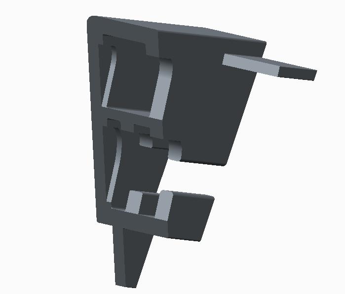
Maybe certain Sections (and intersections between them) are not compatible with Simulate?
An example section (for which this error exists) is attached.
Such section is part of a large frame assembly, joined at mating faces.
Any advice appreciated. Many Thanks