Community Tip - Need to share some code when posting a question or reply? Make sure to use the "Insert code sample" menu option. Learn more! X
- Subscribe to RSS Feed
- Mark Topic as New
- Mark Topic as Read
- Float this Topic for Current User
- Bookmark
- Subscribe
- Mute
- Printer Friendly Page
Split Draft
- Mark as New
- Bookmark
- Subscribe
- Mute
- Subscribe to RSS Feed
- Permalink
- Notify Moderator
Split Draft
Using Creo Elements/Pro 5.0 M210
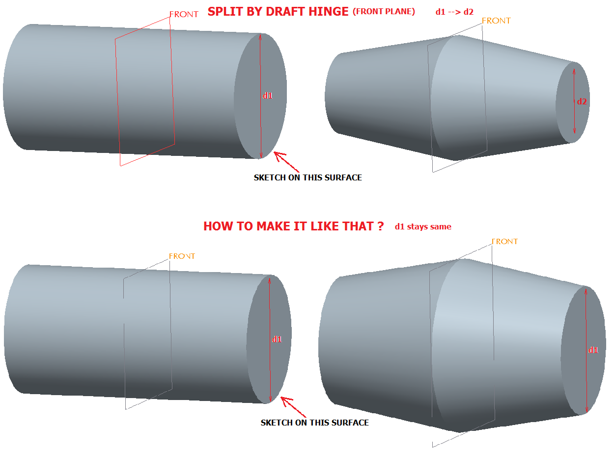
Is there a way to make a draft like shown on picture ?
If i use front plane as draft hinge for splitting. My sketch diameter d1 changes as d2
I want to keep d1 diameter dimension fixed and draft until up to the front plane and then draft down to the d1.

This thread is inactive and closed by the PTC Community Management Team. If you would like to provide a reply and re-open this thread, please notify the moderator and reference the thread. You may also use "Start a topic" button to ask a new question. Please be sure to include what version of the PTC product you are using so another community member knowledgeable about your version may be able to assist.
Solved! Go to Solution.
- Labels:
-
2D Drawing
Accepted Solutions
- Mark as New
- Bookmark
- Subscribe
- Mute
- Subscribe to RSS Feed
- Permalink
- Notify Moderator
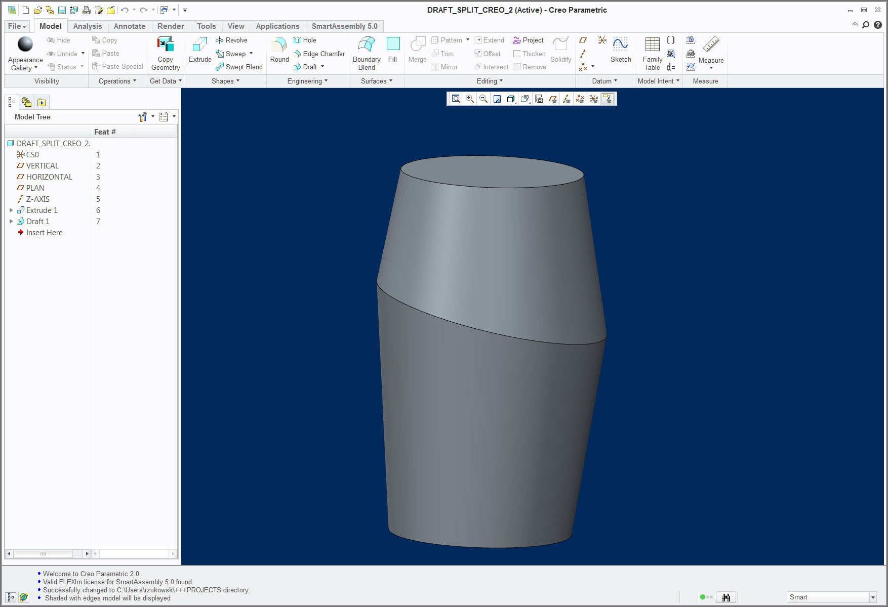
Not sure about Creo Elements/Pro 5.0, but in Creo 2.0 you can:
1. Before selecting anything, go to the "SPLIT" tab and select "split by split object"
2. In the Split object box, "Define" to sketch a line that represents your split location
3. On the "References" tab, select the surface(s) you want to draft
4. In the Draft hinges box, select both top and bottom surfaces of the cylinder, using the CTRL key.
5. Set the pull direction.
6. Set the Side options to "Draft sides dependently"
Hope this helps.
- Mark as New
- Bookmark
- Subscribe
- Mute
- Subscribe to RSS Feed
- Permalink
- Notify Moderator
I think the easiest way to do that would be with a revolve. As you discovered, the draft hinge defines where the size of the drafted surfaces remains the same. I supsect that you're actual model isn't this simple, however.
I can come up with other alternative, but they'd be many more features.
- Mark as New
- Bookmark
- Subscribe
- Mute
- Subscribe to RSS Feed
- Permalink
- Notify Moderator
Not sure about Creo Elements/Pro 5.0, but in Creo 2.0 you can:
1. Before selecting anything, go to the "SPLIT" tab and select "split by split object"
2. In the Split object box, "Define" to sketch a line that represents your split location
3. On the "References" tab, select the surface(s) you want to draft
4. In the Draft hinges box, select both top and bottom surfaces of the cylinder, using the CTRL key.
5. Set the pull direction.
6. Set the Side options to "Draft sides dependently"
Hope this helps.
- Mark as New
- Bookmark
- Subscribe
- Mute
- Subscribe to RSS Feed
- Permalink
- Notify Moderator
You cannot select more than one draft hinge surface, I checked both WF4 & Creo 2.
You can use your method to draft one end at a time by selecting "draft first [or second, as appropriate] side only" and then drafting the other side in a separate feature. It's going to be hard to get the center to line up, if that's important, unless the cylinder is symmetric about the FRONT plane.
- Mark as New
- Bookmark
- Subscribe
- Mute
- Subscribe to RSS Feed
- Permalink
- Notify Moderator
Here are a couple parts that I tried, both Creo 2.0 and WF4.

- Mark as New
- Bookmark
- Subscribe
- Mute
- Subscribe to RSS Feed
- Permalink
- Notify Moderator
Well I've been doing molded parts with Proe for over 17 years and I just learned something new.
I initially selected my draft surfaces first. If you do, you cannot select multiple draft hinge planes until you select "Adjust angles to keep tangency" in the "Angles" tab:
I went back and looked at your instructions more carefully and tried again, defining my split sketch first and it worked fine. Ironically, it did not require selecting "Adjust angles to keep tangency".
This was WF4.
Neat trick, thanks!
- Mark as New
- Bookmark
- Subscribe
- Mute
- Subscribe to RSS Feed
- Permalink
- Notify Moderator
Don't feel bad. One of our designers found this by accident after some "happy clicking".
Makes you wonder how many other helpful tools are hidden in the code that few people know about.
- Mark as New
- Bookmark
- Subscribe
- Mute
- Subscribe to RSS Feed
- Permalink
- Notify Moderator
What's frustrating is that if you start with the draft surfaces, as seems to be the expected workflow, it simply isn't possible.
I agree, there are likely many helpful tools buried in there somewhere. Heck, some aspects like IDD and ISDX have interfaces that seem to be designed to prevent you from discovering things.


