
Turn on suggestions
Auto-suggest helps you quickly narrow down your search results by suggesting possible matches as you type.
Showing results for
Please log in to access translation
Turn on suggestions
Auto-suggest helps you quickly narrow down your search results by suggesting possible matches as you type.
Showing results for
Community Tip - Want the oppurtunity to discuss enhancements to PTC products? Join a working group! X
- Community
- Creo+ and Creo Parametric
- 3D Part & Assembly Design
- Re: Weld Suppression?
Translate the entire conversation x
Please log in to access translation
Options
- Subscribe to RSS Feed
- Mark Topic as New
- Mark Topic as Read
- Float this Topic for Current User
- Bookmark
- Subscribe
- Mute
- Printer Friendly Page
Weld Suppression?
Jul 08, 2016
06:20 AM
- Mark as New
- Bookmark
- Subscribe
- Mute
- Subscribe to RSS Feed
- Permalink
- Notify Moderator
Please log in to access translation
Jul 08, 2016
06:20 AM
Weld Suppression?
I'm having some difficulty with Creo Simulation 2.0 using perimeter welds. For model that I have created a perimeter weld feature, every time I start the simulation the weld that I have created and the contact interface that I have also created are suppressed.
Is there a way to make the application accept this joining condition?
Is there a proper way to make the perimeter weld work?
Should I not use the contact interface and the weld feature together?
I would greatly appreciate any help with my issue and/or any tips.
This thread is inactive and closed by the PTC Community Management Team. If you would like to provide a reply and re-open this thread, please notify the moderator and reference the thread. You may also use "Start a topic" button to ask a new question. Please be sure to include what version of the PTC product you are using so another community member knowledgeable about your version may be able to assist.
Solved! Go to Solution.
Labels:
- Labels:
-
General
ACCEPTED SOLUTION
Accepted Solutions
Jul 18, 2016
12:50 PM
- Mark as New
- Bookmark
- Subscribe
- Mute
- Subscribe to RSS Feed
- Permalink
- Notify Moderator
Please log in to access translation
Jul 18, 2016
12:50 PM
John,
end, spot, perimeter and weld features are shells only.
Shells can be in 3-d assemblies.
Welds do not work with solids
You need another method.
Create a surface region on the side of your doubler that is in 'contact'
The surface region defines a border that will become bonded.
Parts that touch are assumed bonded.
Create a free/contact between the surface region and the mating part leaving the border bonded.
All will be solids
atb
Charles
7 REPLIES 7
Jul 08, 2016
03:16 PM
- Mark as New
- Bookmark
- Subscribe
- Mute
- Subscribe to RSS Feed
- Permalink
- Notify Moderator
Please log in to access translation
Jul 08, 2016
03:16 PM
John,
Can you give a bit more detail with respect to how the contact and the perimeter weld cooperate?
General comments -
Perimeter welds - doublers; usually
Only shells
Contacts don't work with shells (hence suppression)
Space between is 'air'
Doublers add an 'indicative stiffness'; stresses are not trustworthy.
Next bunch of questions would include:
Why do you need the perimeter weld?
What do you want to find out?
As Steven suggests, any pictures/models?
Jul 18, 2016
11:10 AM
- Mark as New
- Bookmark
- Subscribe
- Mute
- Subscribe to RSS Feed
- Permalink
- Notify Moderator
Please log in to access translation
Jul 18, 2016
11:10 AM
Charles,
When I run the model with both the contact and weld unsuppressed, I get a warning that informs me that the they have become suppressed, though the results show something different.
Upon running a another design iteration, both have, in fact, been suppressed.
So you can not use the perimeter weld at all on 3D assemblies?
I need the perimeter weld to join the pieces together, in order to avoid the surfaces from being bonded, which would give me an unrealistic results.
Jul 18, 2016
12:50 PM
- Mark as New
- Bookmark
- Subscribe
- Mute
- Subscribe to RSS Feed
- Permalink
- Notify Moderator
Please log in to access translation
Jul 18, 2016
12:50 PM
John,
end, spot, perimeter and weld features are shells only.
Shells can be in 3-d assemblies.
Welds do not work with solids
You need another method.
Create a surface region on the side of your doubler that is in 'contact'
The surface region defines a border that will become bonded.
Parts that touch are assumed bonded.
Create a free/contact between the surface region and the mating part leaving the border bonded.
All will be solids
atb
Charles
Jul 18, 2016
10:52 AM
- Mark as New
- Bookmark
- Subscribe
- Mute
- Subscribe to RSS Feed
- Permalink
- Notify Moderator
Please log in to access translation
Jul 18, 2016
10:52 AM
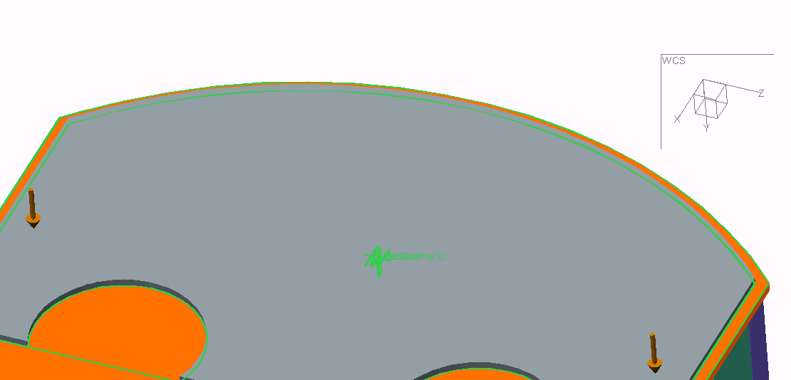
Steven,
The contact is is between two surfaces have a perimeter weld around the border.
(I apologize for the terrible picture.)
Jul 18, 2016
12:57 PM
- Mark as New
- Bookmark
- Subscribe
- Mute
- Subscribe to RSS Feed
- Permalink
- Notify Moderator
Please log in to access translation
Jul 18, 2016
12:57 PM
Hi John,
Have you tried adding a surface region to both parts that your are assigning the contact region too to set the boundary for the weld penetration?
Thanks,
Don Anderson
Aug 22, 2016
08:22 AM
- Mark as New
- Bookmark
- Subscribe
- Mute
- Subscribe to RSS Feed
- Permalink
- Notify Moderator
Please log in to access translation
Aug 22, 2016
08:22 AM
Don,
Is that not what Charles was suggesting?
---------------
Creating a surface region does work. Now I can create the appropriate contact and bonded interfaces.
Thanks Charles and Don.
Aug 23, 2016
10:52 AM
- Mark as New
- Bookmark
- Subscribe
- Mute
- Subscribe to RSS Feed
- Permalink
- Notify Moderator
Please log in to access translation
Aug 23, 2016
10:52 AM
Yes, what John said, his post was not showing when I replied.


