
Turn on suggestions
Auto-suggest helps you quickly narrow down your search results by suggesting possible matches as you type.
Showing results for
Please log in to access translation
Turn on suggestions
Auto-suggest helps you quickly narrow down your search results by suggesting possible matches as you type.
Showing results for
Community Tip - Did you get called away in the middle of writing a post? Don't worry you can find your unfinished post later in the Drafts section of your profile page. X
- Community
- Creo+ and Creo Parametric
- Analysis
- Re: Modeling Fasteners through multiple parts.
Translate the entire conversation x
Please log in to access translation
Options
- Subscribe to RSS Feed
- Mark Topic as New
- Mark Topic as Read
- Float this Topic for Current User
- Bookmark
- Subscribe
- Mute
- Printer Friendly Page
Modeling Fasteners through multiple parts.
Jan 17, 2019
03:55 PM
- Mark as New
- Bookmark
- Subscribe
- Mute
- Subscribe to RSS Feed
- Permalink
- Notify Moderator
Please log in to access translation
Jan 17, 2019
03:55 PM
Modeling Fasteners through multiple parts.
Hi, I have an assembly which consists of a circuit card assembly (CCA) and a EMI clam shell on each side of the CCA. The screw clamps the CCA in between the two clamshells. The fastener model will not work on this. I have tried "rigid links" etc, no luck there.
Is there anything else to try? I analyzed this model with all the parts fused together, and gives very high natural frequencies, etc.
Thanks in advance

Labels:
- Labels:
-
Simulate
9 REPLIES 9
Jan 17, 2019
04:58 PM
- Mark as New
- Bookmark
- Subscribe
- Mute
- Subscribe to RSS Feed
- Permalink
- Notify Moderator
Please log in to access translation
Jan 17, 2019
04:58 PM
What version of Creo?
Are you using Windchill or another PLM for your model libraries?
Is this a stand-alone screw or family table member?
Are you trying to do this with Intelligent Fastener module?
Jan 17, 2019
07:22 PM
- Mark as New
- Bookmark
- Subscribe
- Mute
- Subscribe to RSS Feed
- Permalink
- Notify Moderator
Please log in to access translation
Jan 17, 2019
07:22 PM
Hello
1) CREO 2.0
2) Windchill.
3) Family Table
4) I am using the fastener model in Creo/Simulate.
Jan 18, 2019
04:54 AM
- Mark as New
- Bookmark
- Subscribe
- Mute
- Subscribe to RSS Feed
- Permalink
- Notify Moderator
Please log in to access translation
Jan 18, 2019
04:54 AM
"...The fastener model will not work on this..."
why?
Jan 18, 2019
09:45 AM
- Mark as New
- Bookmark
- Subscribe
- Mute
- Subscribe to RSS Feed
- Permalink
- Notify Moderator
Please log in to access translation
Jan 18, 2019
09:45 AM
I am thinking there are issues with your model beyond just the way the fasteners are modeled. I use rigid links for fasteners in modal analysis quite often and they work fine for me. If your model-setup interface-default is bonded that may be the start of the problem. Look at the review-model showing the bonds/contacts/rigids. Try limiting connection areas using surface regions and interfaces rather than letting the model connect everywhere it is line-to-line geometry. For example make a region the size of the washers and only bond there between all three the parts. BTW The image you show seems like it should allow a screw fastener idealization. There are some specific ways the geometry must be made before it allows the fastener idealization, such as perfectly concentric holes, perfect cylinder holes (not tapered with draft) and screw (and nut for bolts) head plane perfectly normal to the hole axis. Your model geometry is probably fine, I just wanted to mention those restrictions.
Jan 18, 2019
10:17 AM
- Mark as New
- Bookmark
- Subscribe
- Mute
- Subscribe to RSS Feed
- Permalink
- Notify Moderator
Please log in to access translation
Jan 18, 2019
10:17 AM
Hello
Thank you for your input. The screw idealization will not work because it only works with the parts that are connected. The in between part is not affected. I like your idea of the ridge links between the parts. I think I'll try the rigid link idea first. Then the screw idealization between the two outer parts with the links for that preload and stiffness.
Thank you very much.
Rich Hilson
Jan 18, 2019
11:20 AM
- Mark as New
- Bookmark
- Subscribe
- Mute
- Subscribe to RSS Feed
- Permalink
- Notify Moderator
Please log in to access translation
Jan 18, 2019
11:20 AM
Your welcome,
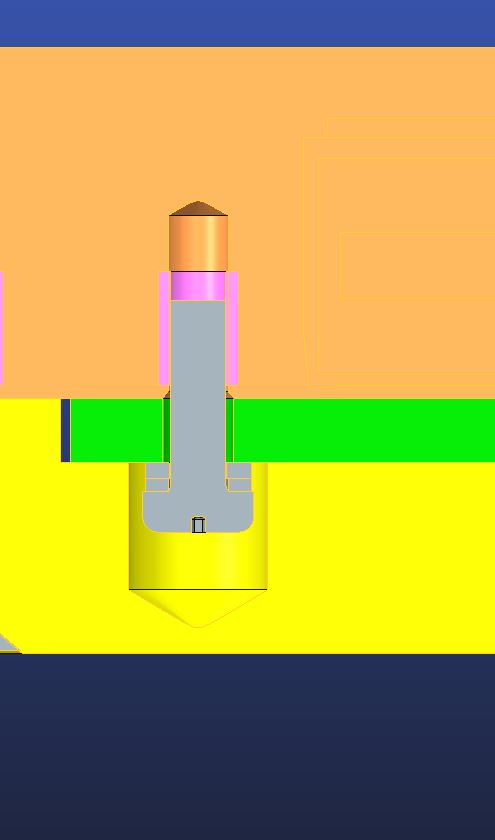
I do not see a sandwiched part in your image. I see the green part connecting to the brown in your image. The yellow is not shown as part of the sandwich, not even held by the screw. I agree that the fastener idealization cannot connect with a middle sandwiched component... I am just not seeing that in your model.
Jan 18, 2019
12:50 PM
- Mark as New
- Bookmark
- Subscribe
- Mute
- Subscribe to RSS Feed
- Permalink
- Notify Moderator
Please log in to access translation
Jan 18, 2019
12:50 PM

Hi you are correct. Here is the correct view.
Jan 21, 2019
02:27 AM
- Mark as New
- Bookmark
- Subscribe
- Mute
- Subscribe to RSS Feed
- Permalink
- Notify Moderator
Please log in to access translation
Jan 21, 2019
02:27 AM
Hi everybody,
in Simulate the screws/bolts idealization works only between TWO parts. If you have more than two parts you cannot use that kind of idealization.
If your focus is analize what happen exactly "under the washers" and/or exactly at the interface around the hole between plates green and brown (e.g.: you are interested to see the shear force the friction exchanges) then you must put contacts interfaces. Then you can use a pre-loded point-point spring or a point-point beam with heat load (there is also a third way, namely by using the preload feature over a solid screw...but this feature was introduced from Creo 3). In this manner you can get the best quality results against much more computing time because it's a non-linear anlysis.
If you don't need all of this, I reccomend you to use bonded interfaces.
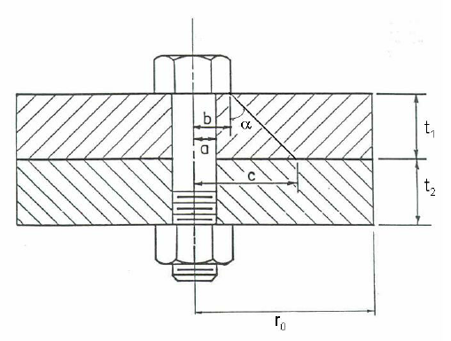
Remember that under screw's head and nut, that in the feature are indicated with the parameter "Fastner Head and Nut Diameter", you need to have "material" to create the cone of compressed material beetwen plates (see attached image). So, in case of linear analysis, I suggest you to reove any washers.
Mar 01, 2019
01:24 PM
- Mark as New
- Bookmark
- Subscribe
- Mute
- Subscribe to RSS Feed
- Permalink
- Notify Moderator
Please log in to access translation
Mar 01, 2019
01:24 PM
Thank you very much graulini.
Announcements


Top Tags
