
Turn on suggestions
Auto-suggest helps you quickly narrow down your search results by suggesting possible matches as you type.
Showing results for
Please log in to access translation
Turn on suggestions
Auto-suggest helps you quickly narrow down your search results by suggesting possible matches as you type.
Showing results for
Community Tip - Have a PTC product question you need answered fast? Chances are someone has asked it before. Learn about the community search. X
- Community
- Creo+ and Creo Parametric
- Analysis
- Re: Shaft FEA simulation torque and constraints
Translate the entire conversation x
Please log in to access translation
Options
- Subscribe to RSS Feed
- Mark Topic as New
- Mark Topic as Read
- Float this Topic for Current User
- Bookmark
- Subscribe
- Mute
- Printer Friendly Page
Shaft FEA simulation torque and constraints
Oct 11, 2018
10:12 AM
- Mark as New
- Bookmark
- Subscribe
- Mute
- Subscribe to RSS Feed
- Permalink
- Notify Moderator
Please log in to access translation
Oct 11, 2018
10:12 AM
Shaft FEA simulation torque and constraints
Hello everyone,
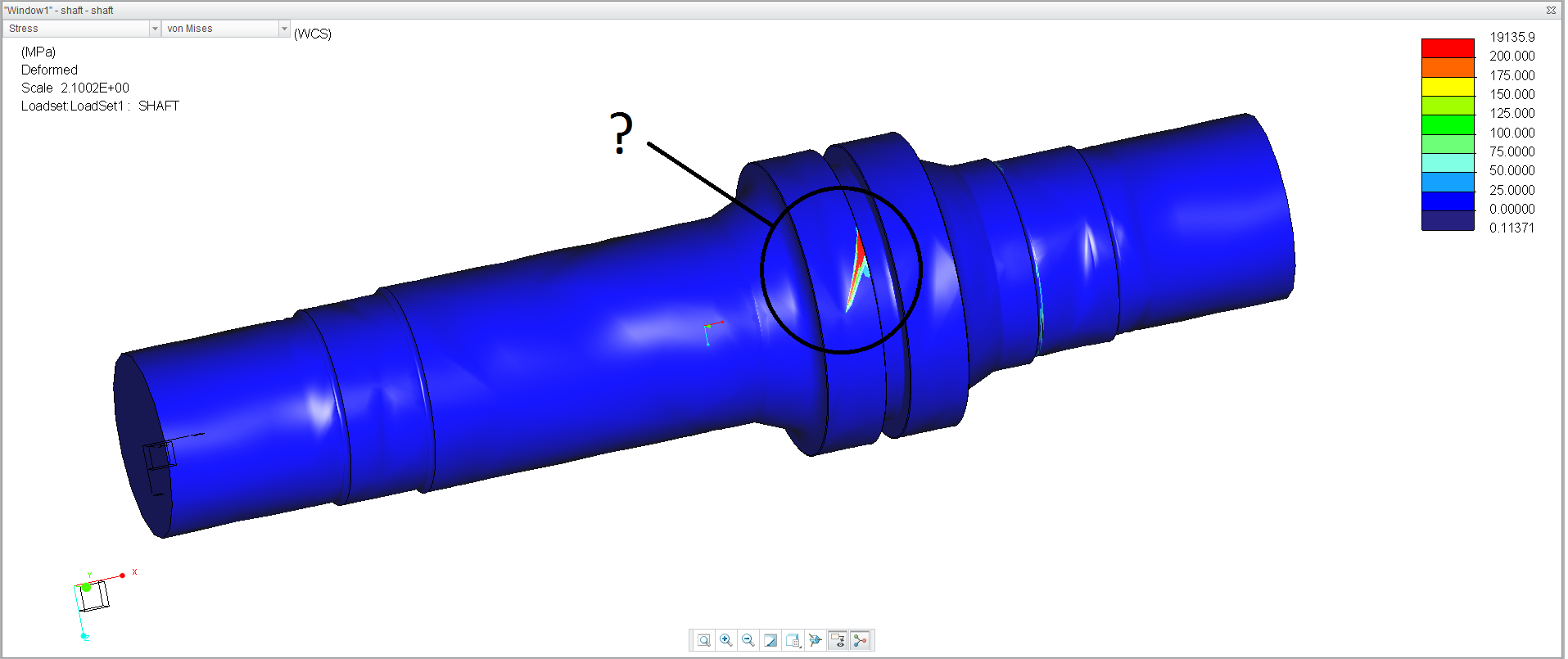
I am trying to perform a fea on a shaft with 2 inputs (10000 lb*ft), supported by 2 bearings.
Instead of putting a constraint at the output gear I thought it would be better to apply a torque
opposite to the input torque, in this case -20000 lb*ft.
The stress and deflection I obtain don't seem correct. The shaft rotates in the direction of
the input torque (more than one full rotation, the output torque doesn't seem to have any effect), it shrinks and on the output gear it
is showed a high localized stressed area, which I cannot justify.
If I substitute the output torque with a constraint that fix rotations the result seems to be correct, but
I would like to investigate the reason why applying opposite torques doesn't work.
I add that if I run the model with only input torques the fea still runs, even if I should get an error because the system is not isostatic and the shaft can rotate on its axis.
I hope someone can help me on this.
Thank you
Daniele
Solved! Go to Solution.
ACCEPTED SOLUTION
Accepted Solutions
Oct 12, 2018
04:38 AM
- Mark as New
- Bookmark
- Subscribe
- Mute
- Subscribe to RSS Feed
- Permalink
- Notify Moderator
Please log in to access translation

11 REPLIES 11
Oct 12, 2018
04:38 AM
- Mark as New
- Bookmark
- Subscribe
- Mute
- Subscribe to RSS Feed
- Permalink
- Notify Moderator
Please log in to access translation
Oct 12, 2018
09:43 AM
- Mark as New
- Bookmark
- Subscribe
- Mute
- Subscribe to RSS Feed
- Permalink
- Notify Moderator
Please log in to access translation
Oct 12, 2018
09:43 AM
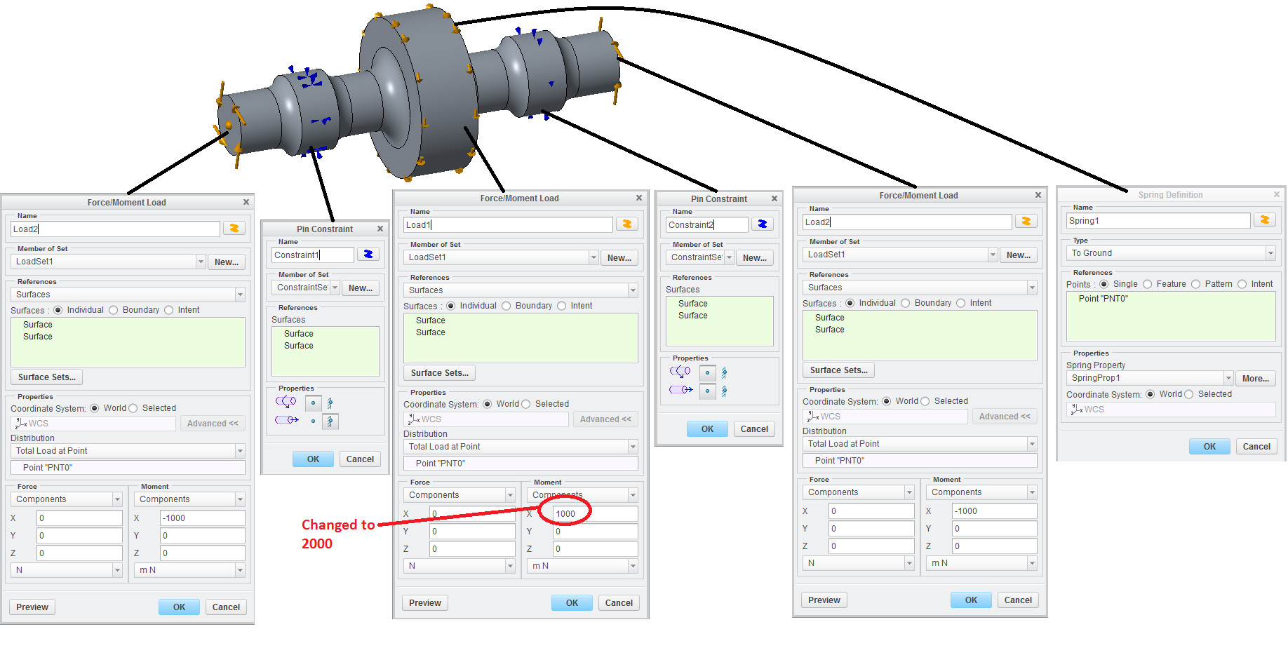
I checked your model. The torques you applied are not balanced, if I balance them I get a result
really similar to mine, with a concentrated spot on the central gear and extremely high stresses. From the deflections I see that the shaft is spinning even if torques are balanced.
Oct 15, 2018
07:31 AM
- Mark as New
- Bookmark
- Subscribe
- Mute
- Subscribe to RSS Feed
- Permalink
- Notify Moderator
Please log in to access translation

Oct 15, 2018
08:36 AM
- Mark as New
- Bookmark
- Subscribe
- Mute
- Subscribe to RSS Feed
- Permalink
- Notify Moderator
Please log in to access translation
Oct 15, 2018
08:36 AM
Yes, your model was correct.
Maybe there was confusion because dnogas model has two separate 1000 loads (each end) and you combined two ends into one.
dnogas model still needs +2000. yours needs +1000. The models are different geometry and units anyhow and really just the spring was the "trick" to create truly static to stop the 0.683032 MX residual.

Oct 15, 2018
09:35 AM
- Mark as New
- Bookmark
- Subscribe
- Mute
- Subscribe to RSS Feed
- Permalink
- Notify Moderator
Please log in to access translation
Oct 15, 2018
09:35 AM
Skunks, I apologize. Your torque was correct! I didn't see you applied it on both sides of the shaft as one load.
I think you got the solution.
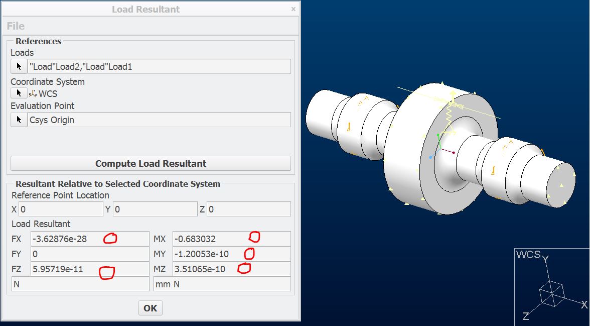
It is good to share that under the tab Loads->Load Resultant->It is possible to select multiple loads and compute the resultant. In this case it is particularly useful to select all loads and see how much is the "unbalanced" torque.
I still have to play with the model and adjust the spring properties. As a different approach, I'm thinking to apply an additional torque to balance the small residual.
Oct 12, 2018
01:51 PM
- Mark as New
- Bookmark
- Subscribe
- Mute
- Subscribe to RSS Feed
- Permalink
- Notify Moderator
Please log in to access translation
Oct 12, 2018
01:51 PM
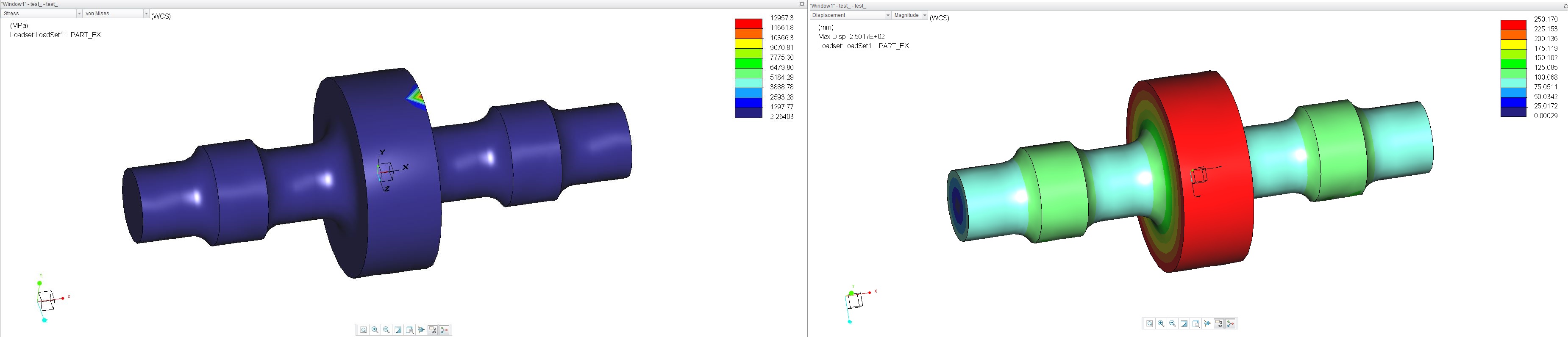
I think I found the issue. If the spring is too weak it does not work. The problem was that it is such a large heavy part, the residuals are higher than expected.
If I use this property and Skunks spring, the results are great.

To see the residuals try Loads - review total load and look at the tiny errors.
For example...

Also, I have some concern about your constraints not allowing bending. Maybe the bearings are not so perfect as that. Skunks has an example with shafts that can bend at their bearings. One of us will probably post a link to it.
Oct 15, 2018
09:40 AM
- Mark as New
- Bookmark
- Subscribe
- Mute
- Subscribe to RSS Feed
- Permalink
- Notify Moderator
Please log in to access translation
Oct 15, 2018
09:40 AM
Thank you for sharing the 2 links, good to know.
Oct 17, 2018
12:35 PM
- Mark as New
- Bookmark
- Subscribe
- Mute
- Subscribe to RSS Feed
- Permalink
- Notify Moderator
Please log in to access translation
Oct 17, 2018
12:35 PM
I want to add a final comment.
When using the command "Review total load" I have sadly noticed that the resultants are not always correct, error is generally small (see this topic), but could affect comparisons with hand calculations. So be aware of this especially when balancing complex shafts.
Oct 17, 2018
04:32 PM
- Mark as New
- Bookmark
- Subscribe
- Mute
- Subscribe to RSS Feed
- Permalink
- Notify Moderator
Please log in to access translation

Oct 12, 2018
12:30 PM
- Mark as New
- Bookmark
- Subscribe
- Mute
- Subscribe to RSS Feed
- Permalink
- Notify Moderator
Please log in to access translation
Oct 12, 2018
12:30 PM
Your problem is that Input_left and Input_right are not applied to the model. They are applied to surfaces that are not part of the model from Extrude1 and Extrude2. You need to instead create surface or volume regions on the simulate side to split the regions on the ends of the part. In effect the full 20000 ft-lbf was applied to skunks spring instead of the small residual.
Finally, two choices to remove the small residual. (EDIT -choice A requires no constraints, only loads like a free body diagram so the constraints would have to be replaced with their reaction loads)
A. turn on Inertia relief in your analysis definition. This will account for small numerical discrepancies that cause rotation.
B. use skunks spring to arrest these small forces.
I believe the reason it did not error out as underconstrained may be because of the gravity load you applied, but I did not test this theory. I say this because inertia relief is also a type of automatic gravity load.
-regards
Oct 12, 2018
12:58 PM
- Mark as New
- Bookmark
- Subscribe
- Mute
- Subscribe to RSS Feed
- Permalink
- Notify Moderator
Please log in to access translation
Oct 12, 2018
12:58 PM
Actually, the applied input torques always generate stresses in the shaft, meaning they're being applied by the software. I will try anyway to apply the input torques to volume regions.
I don't want to use the "inertia relief" feature because the shaft is subjected to gravity and, most importantly, there are radial loads which are not balanced (left and right torque comes from belts, hence a radial load is generated. The central gear as well has a radial load to transmit torque)
What do you mean by "In effect the full 20000 ft-lbf was applied to skunks spring instead of the small residual"?
Thank you
Announcements


Top Tags
